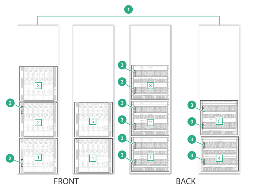
Three primary enclosures (frames) connected to two remote enclosures (frames) cabling example
NOTE:
In HPE OneView, HPE Synergy frames are referred to as enclosures.
NOTE:
This cabling example does not cover power or production network cabling.
This example shows cabling three primary enclosures (frames) to two remote enclosures (frames).
Primary enclosures (frames) include HPE Synergy Composers. Remote enclosures (frames) do not contain HPE Synergy Composers.
This same cabling methodology can be used up to the number of frames supported as defined in the
HPE OneView Support Matrix for HPE Synergy (http://www.hpe.com/info/synergy-docs).
Prerequisites
Figure 24: Required components for primary and remote enclosures (frames) cabled to the management network
Item
Description
Quantity
1
HPE Synergy 12000 frames
Primary enclosures (frames) [1], [2], [3]
Remote enclosures (frames) [4], [5]
5
2
HPE Synergy Composer
2
3
HPE Synergy Frame Link Module
10
Procedure
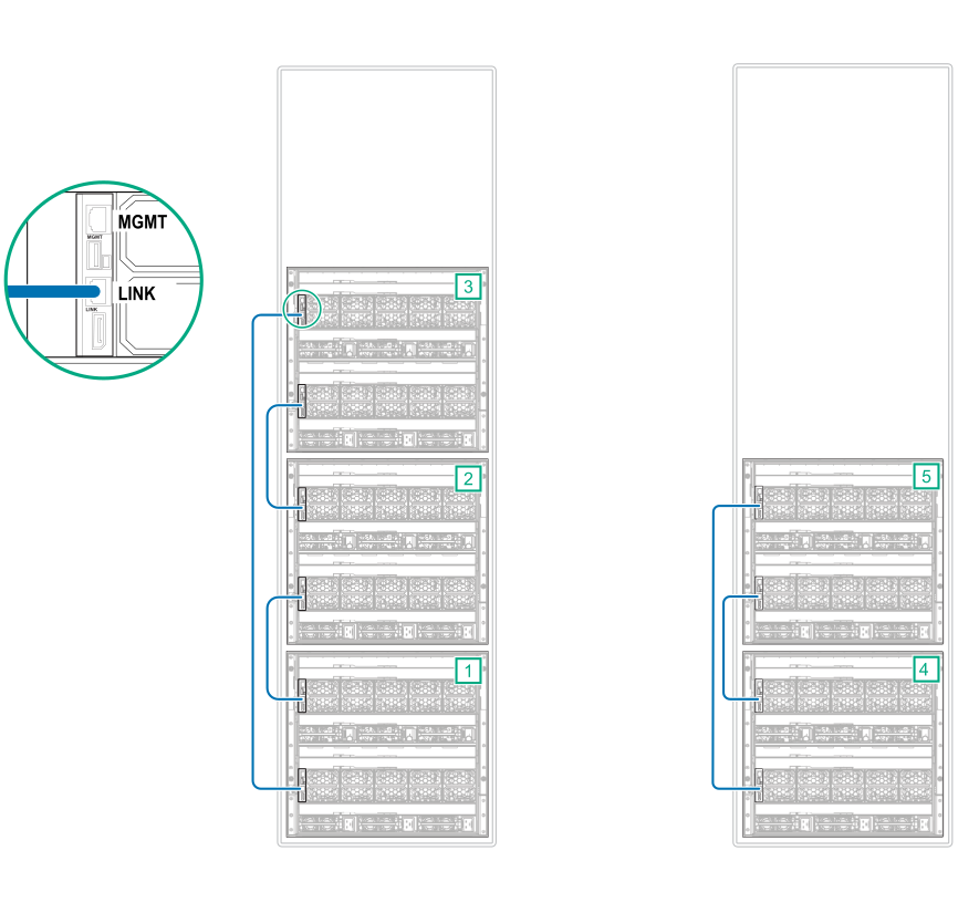
Using CAT6A cables, connect the
LINK ports on the primary enclosures (frames) together.
Using CAT6A cables, connect the
LINK ports on the remote enclosures (frames) together.
Figure 25: LINK port cabling for primary and remote enclosures (frames) cabled to the management network
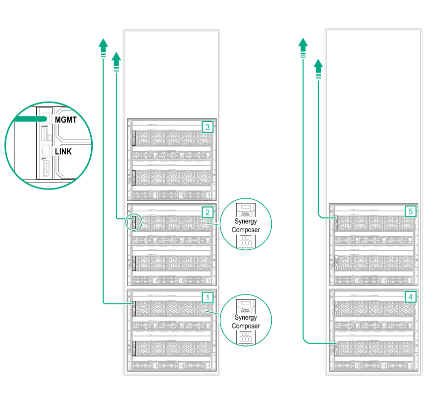
Connect Ethernet cables from two
MGMT ports from the primary enclosures (frames) to the management network.
Connect Ethernet cables from two
MGMT ports from remote enclosures (frames) to the management network.
Figure 26: MGMT ports to management network cabling for primary and remote enclosures (frames) cabled to the management network
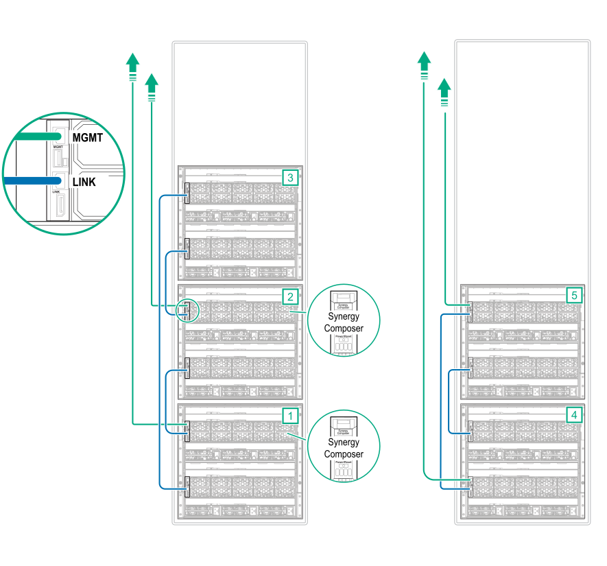
Cabling is complete. The following diagram shows the complete cabling diagram.