Five-frame
HPE Synergy Image Streamer configuration cabling example
NOTE:
This cabling example does not cover power or production network cabling.
Prerequisites
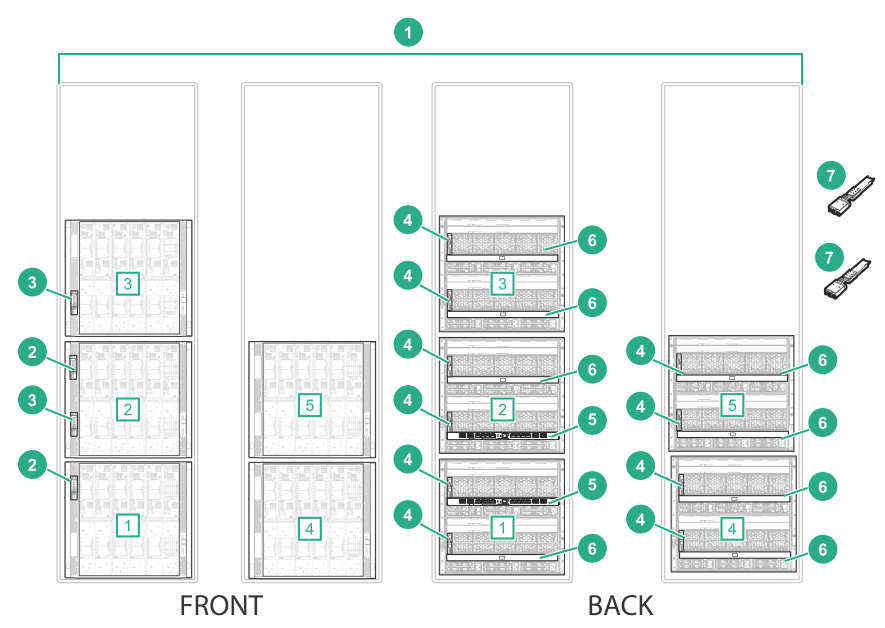
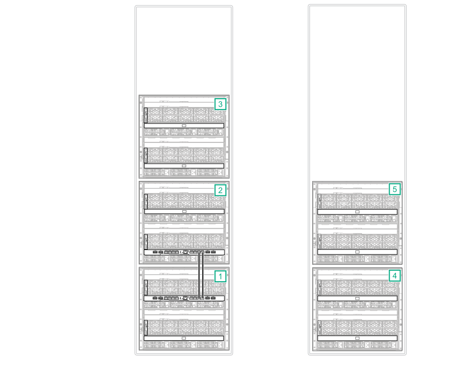
Figure 78: Components required for a five-frame configuration with
HPE Synergy Image Streamer and
2-port FLM
Item
Description
Quantity
1
HPE Synergy frames [1], [2], [3], [4], [5]
5
2
HPE Synergy Composers
2
3
HPE Synergy Image Streamers
2
4
HPE Synergy Frame link modules
10
5
HPE Synergy Virtual Connect SE 40Gb F8 module (master ICM)
2
6
HPE Synergy 10Gb Interconnect Link Module (satellite ICM)
8
7
HPE Synergy Dual 10GBASE-T QSFP+ 30m RJ45 adapter
2
Procedure
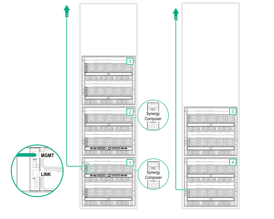
Management cabling
Connect Ethernet cables from two
MGMT ports to the management network.
Figure 79: MGMT port to management network cabling for a five-frame configuration with
HPE Synergy Image Streamer and
2-port FLM
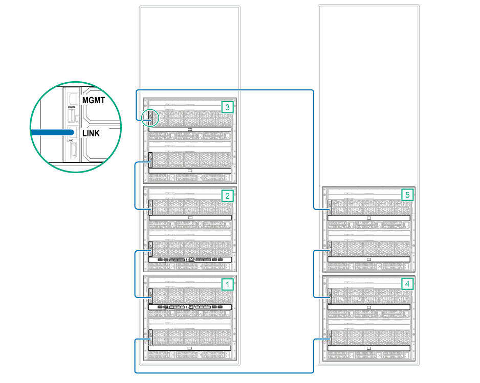
Using CAT6A cables, connect all frame link module
LINK ports together.
Figure 80: LINK port cabling for a five-frame configuration with
HPE Synergy Image Streamer and
2-port FLM
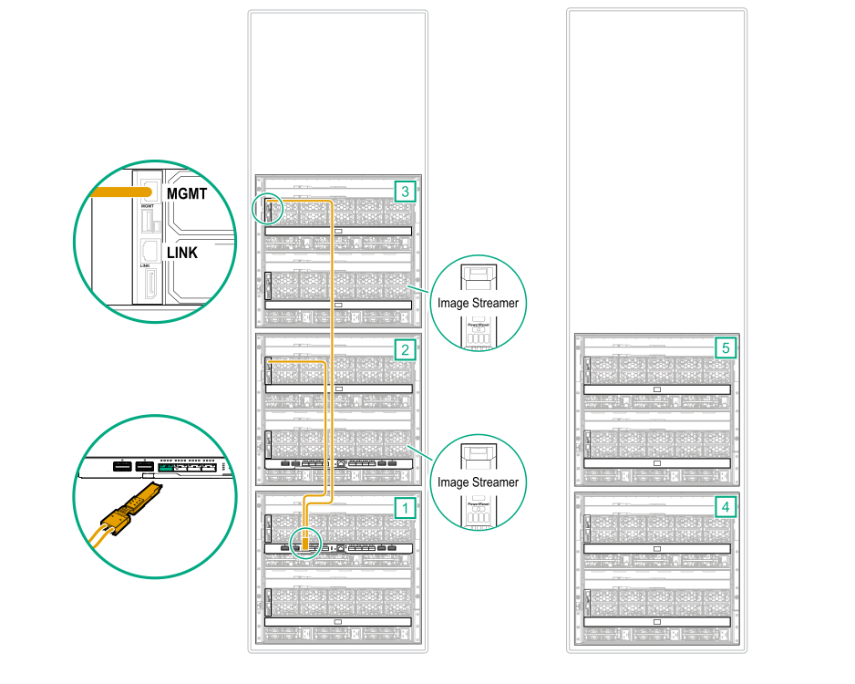
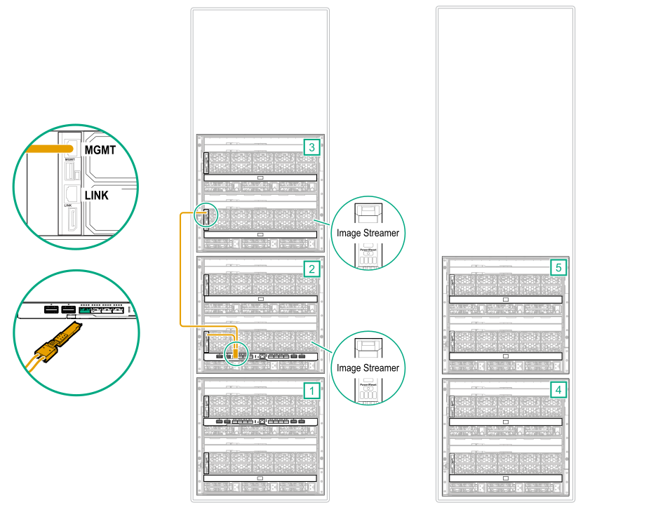
HPE Image Streamer cabling
Connect a CAT6A cable from each
MGMT port in the frames with an HPE Image Streamer installed to the master ICMs.
Connect the bay 1 frame link module
MGMT ports to an
HPE Synergy Dual 10GBASE-T QSFP+ 30m RJ45 adapter.
Connect the
HPE Synergy Dual 10GBASE-T QSFP+ 30m RJ45 adapter to the first
HPE Synergy Virtual Connect SE 40Gb F8 module.
Figure 81: MGMT port to master ICM cabling for a five-frame configuration with
HPE Synergy Image Streamer and
2-port FLM (frame 1)
Connect the bay 2 frame link module
MGMT ports to an
HPE Synergy Dual 10GBASE-T QSFP+ 30m RJ45 adapter.
Connect the
HPE Synergy Dual 10GBASE-T QSFP+ 30m RJ45 adapter to the second
HPE Synergy Virtual Connect SE 40Gb F8 module.
Figure 82: MGMT port to master ICM cabling for a five-frame configuration with
HPE Synergy Image Streamer and
2-port FLM (frame 2)
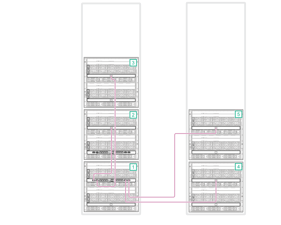
Master and satellite ICM cabling
Connect an interconnect cable from the L1, L2, L3, and L4 ports on the first
master ICM to each
satellite ICM in the same bay.
Port L1 of each
HPE Synergy Virtual Connect SE 40Gb F8 module must be connected to the satellite ICM in the other frame with a
HPE Synergy Virtual Connect SE 40Gb F8 module installed.
Figure 83: Master ICM to satellite ICM cabling for a five-frame configuration with
HPE Synergy Image Streamer and
2-port FLM (frame 1)
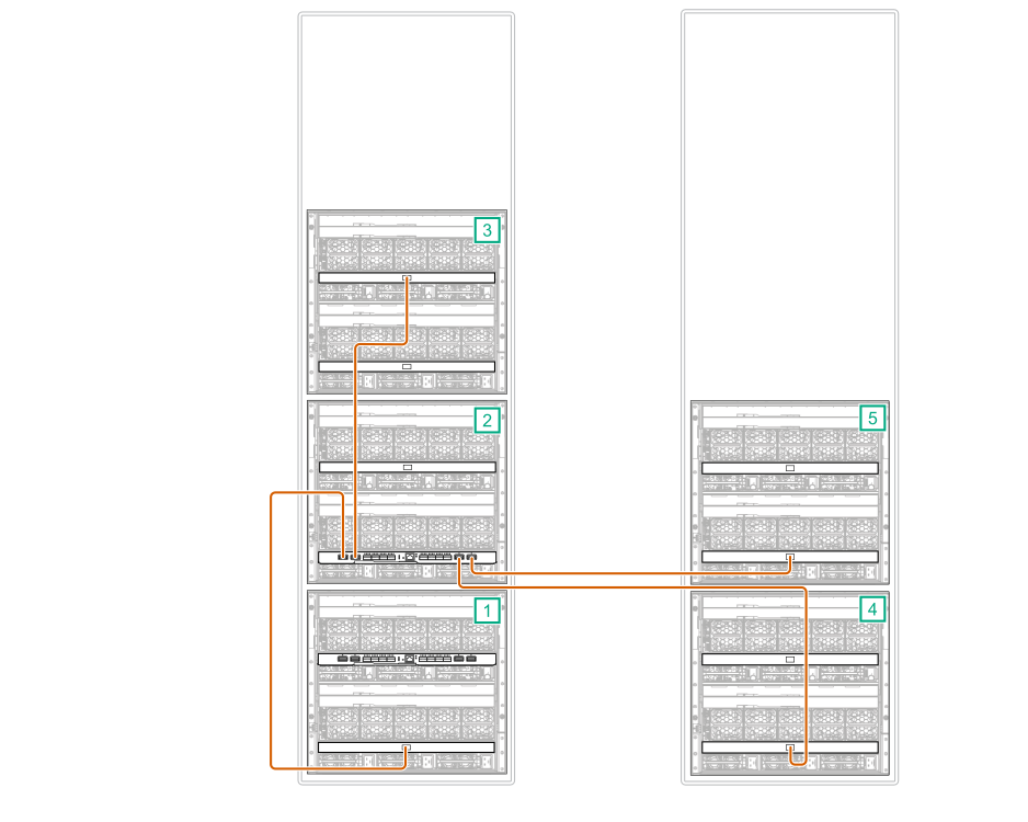
Connect an interconnect cable from the L1, L2, L3, and L4 ports on the second
master ICM to each
satellite ICM in the same bay.
Figure 84: Master ICM to satellite ICM cabling for a five-frame configuration with
HPE Synergy Image Streamer and
2-port FLM (frame 2)
Connect a stacking cable from the first
master ICM to the second
master ICM.
Connect port Q7 on the first
master ICM to port Q7 on the second
master ICM.
Connect port Q8 on the first
master ICM to port Q8 on the second
master ICM.
Figure 85: Stacking cabling for a five-frame configuration with
HPE Synergy Image Streamer and
2-port FLM
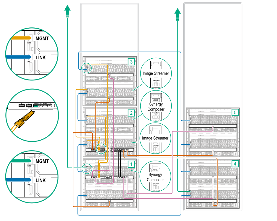
Cabling is complete. The following diagram shows the complete cabling diagram.
Figure 86: Complete cabling for a five-frame configuration with
HPE Synergy Image Streamer and
2-port FLM
 Cabling is complete. The following diagram shows the complete cabling diagram.