Five-frame
HPE Synergy Image Streamer configuration cabling example with
HPE Virtual Connect SE 100Gb F32 Module for HPE Synergy and HPE Synergy 4-Port Frame Link Modules
IMPORTANT:
HPE Synergy 12000 Frames with Composers installed must both have the same type of frame link module installed.
IMPORTANT:
HPE Synergy Image Streamers must be installed in frames with HPE Synergy Frame Link Modules (2-Port).
IMPORTANT:
The management network top-of-rack switch must be the same speed as the cables or transceivers used for
MGMT port cabling.
This cabling scenario covers cabling five frames with HPE Synergy Composer2 and HPE Synergy Image Streamer. Frames with HPE Synergy Image Streamer use 2-Port FLMs. All other frames use 4-Port FLMs.
Prerequisites
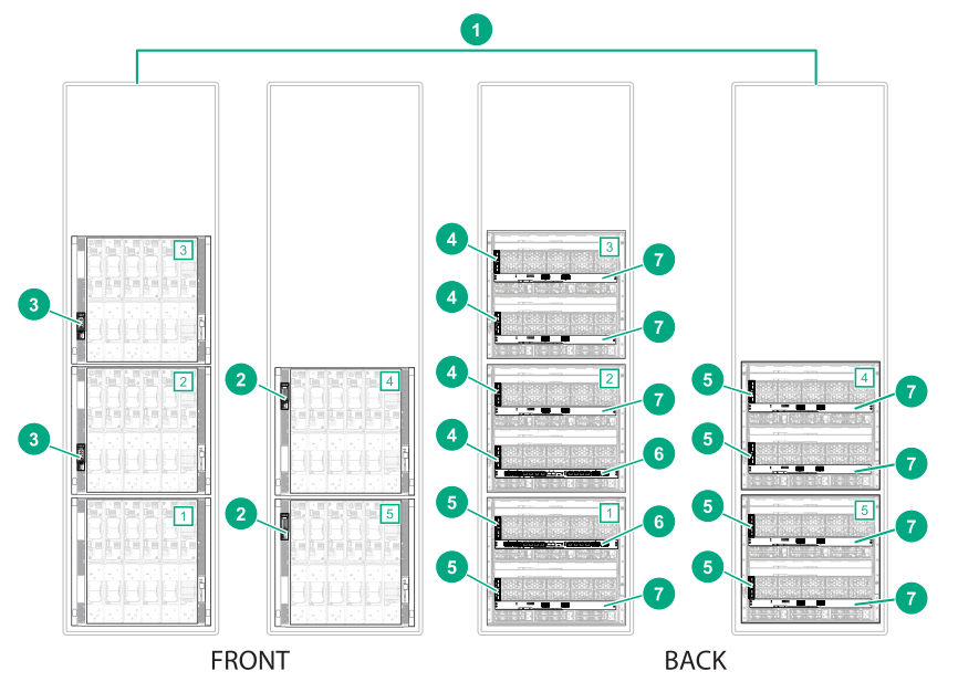
Figure 41: Components required for a five-frame
HPE Synergy configuration with
HPE Synergy Image Streamer and
4-port FLMs
Item
Description
Quantity
1
HPE Synergy frames [1], [2], [3], [4], [5]
5
2
HPE Synergy Composer2
2
3
HPE Synergy Image Streamers
2
4
HPE Synergy Frame Link Module (2-Port FLM)
4
5
HPE Synergy 4-Port Frame Link Module (4-Port FLM)
6
6
HPE Virtual Connect SE 100Gb F32 Module for HPE Synergy (master ICM)
2
7
HPE Synergy 50Gb Interconnect Link Module (satellite ICM)
8
8
10GBase-T SFP+ transceiver (not shown)
6
Procedure
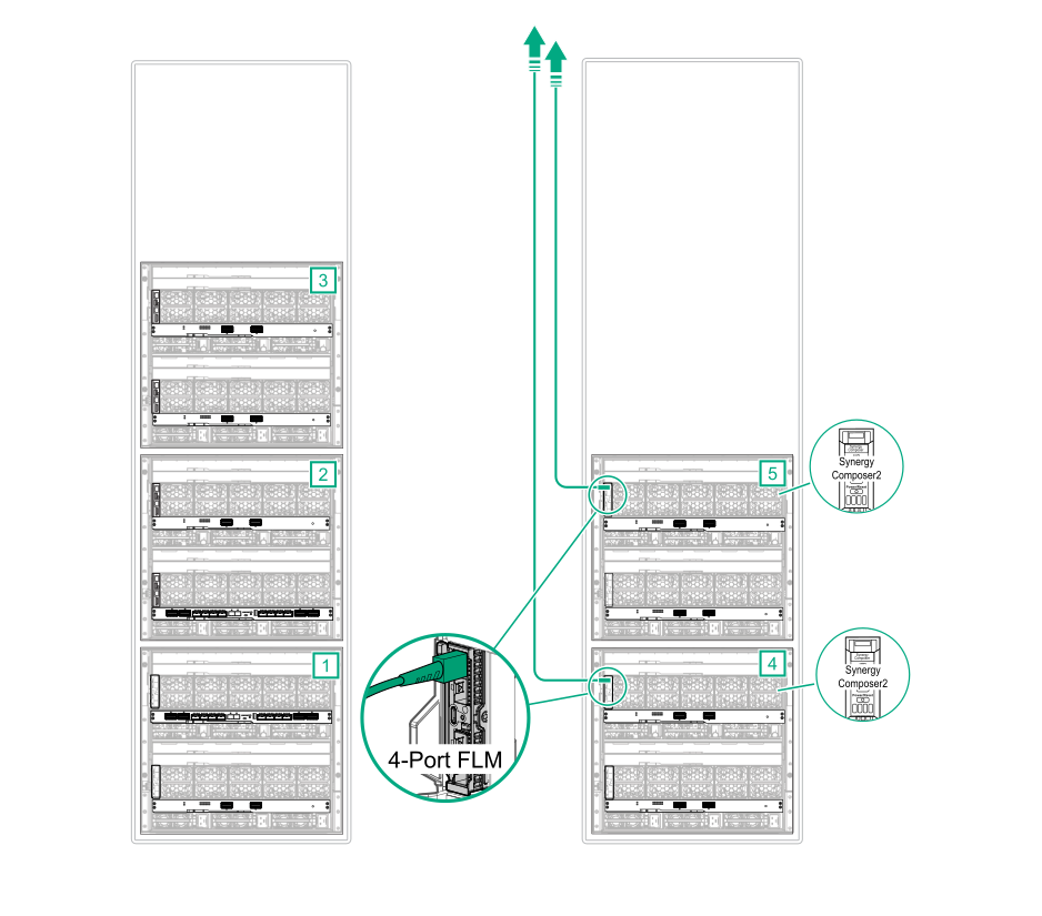
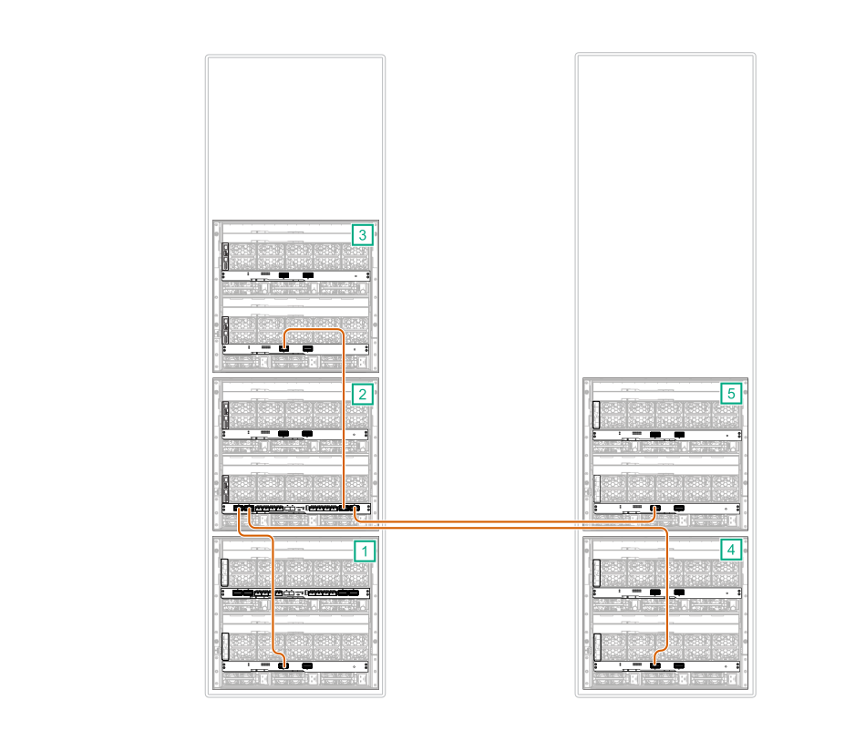
Management cabling
Using
SFP DAC cables cables, connect two 4-Port FLM
MGMT ports to the management network.
NOTE:
The 4-Port FLM
MGMT port supports 1GbE and 10GbE cables and transceivers. The
MGMT port speed is set based on the cables or transceivers used.
NOTE: The 4-Port FLM
MGMT port supports
1000BASE-T SFP Transceiver with CAT5 cables,
10GBase-T SFP+ transceiver with CAT6A cables,
SFP DAC cables,
SFP+ 10Gb DAC cables, and
SFP+ 10Gb transceivers with optical cables. For a complete list of cabling options, see the product QuickSpecs
www.hpe.com/info/qs.
Figure 42: MGMT port to management network cabling for a five-frame
HPE Synergy configuration with
HPE Synergy Image Streamer and
4-port FLMs
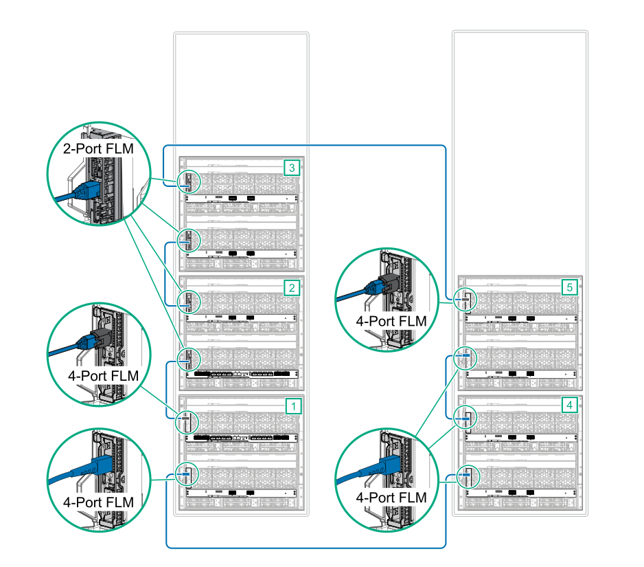
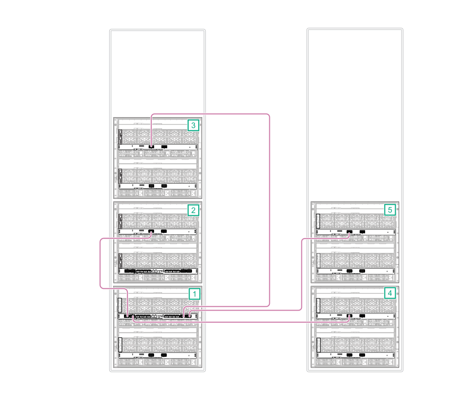
Connect all frame link module
LINK ports together.
Install a
10GBase-T SFP+ transceiver into the 4-Port FLM LINK port in frame 1 bay 1 and in frame 5 bay 1.
Use CAT6A cables to connect the 2-Port FLM
LINK
ports to the
10GBase-T SFP+ transceiver installed in the 4-Port FLM
LINK
ports.
Connect the 2-Port FLM
LINK port in frame 3 bay 1 to the 4-Port FLM
LINK port in frame 4 bay 1.
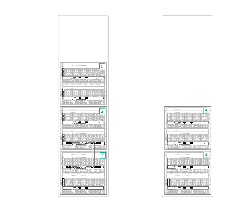
Connect the 2-Port FLM
LINK port in frame 2 bay 2 to the 4-Port FLM
LINK port in frame 1 bay 1.
Use a
SFP+ 10Gb DAC cable to connect 4-Port FLM
LINK ports to 4-Port FLM
LINK ports.
NOTE: The 4-Port FLM
LINK port supports
10GBase-T SFP+ transceiver with CAT6A cables,
SFP+ 10Gb DAC cables, and
SFP+ 10Gb transceivers with optical cables. For a complete list of cabling options, see the product QuickSpecs
www.hpe.com/info/qs.
Connect the frame 1 bay 2 4-Port FLM
LINK port to the frame 5 bay 2 4-Port FLM
LINK port.
Connect the frame 5 bay 1 4-Port FLM
LINK port to the frame 4 bay 2 4-Port FLM
LINK port.
Use a CAT6A cable to connect the frame 3 bay 2 2-Port FLM
LINK port to the frame 2 bay 1 2-Port FLM
LINK port.
Figure 43: LINK port cabling (4-Port FLM to 2-Port FLM) for a five-frame
HPE Synergy configuration with
HPE Synergy Image Streamer and
4-port FLMs
HPE Image Streamer cabling
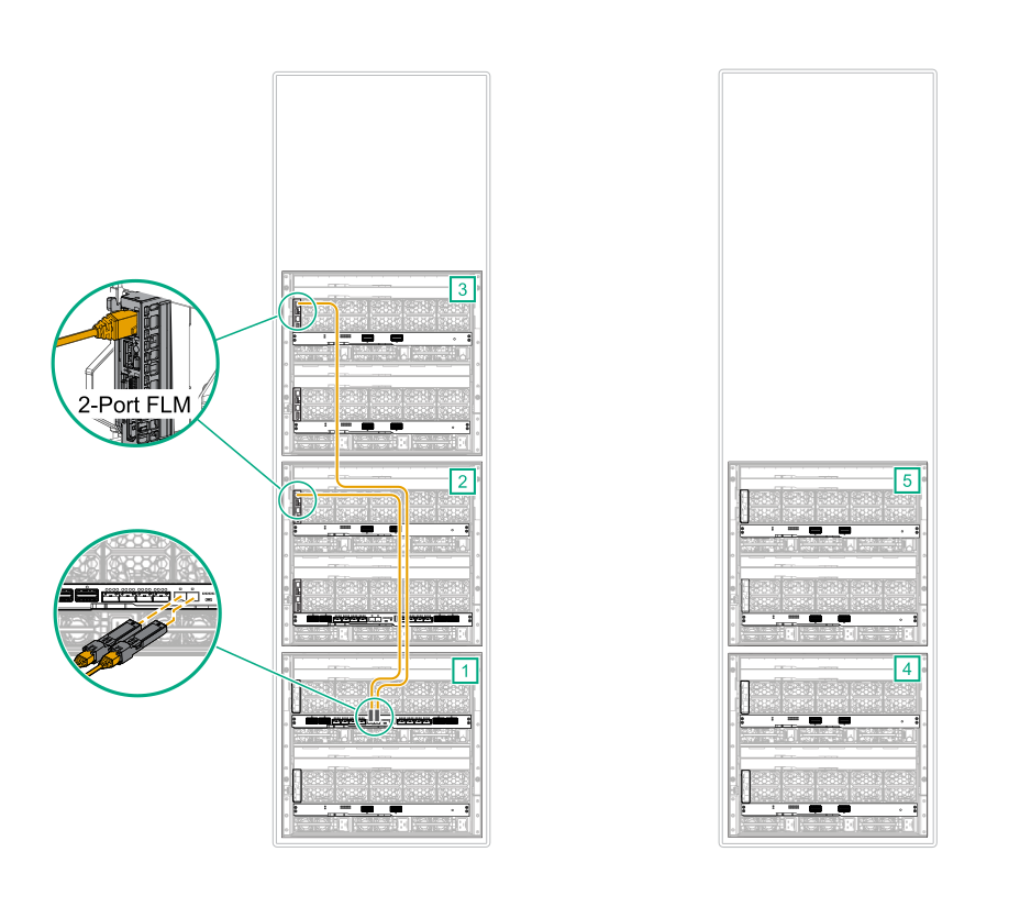
Connect a CAT6A cable from each
MGMT port in the frames with an HPE Image Streamer installed to the master ICMs.
Connect the bay 1 frame link module
MGMT port from each Image Streamer frame to an
10GBase-T SFP+ transceiver.
Connect each
10GBase-T SFP+ transceiver to the X1 and X2 ports on the primary master ICM in frame 1.
Figure 44: MGMT port to master ICM cabling for a five-frame
HPE Synergy configuration with
HPE Synergy Image Streamer and
4-port FLMs (frame 1)
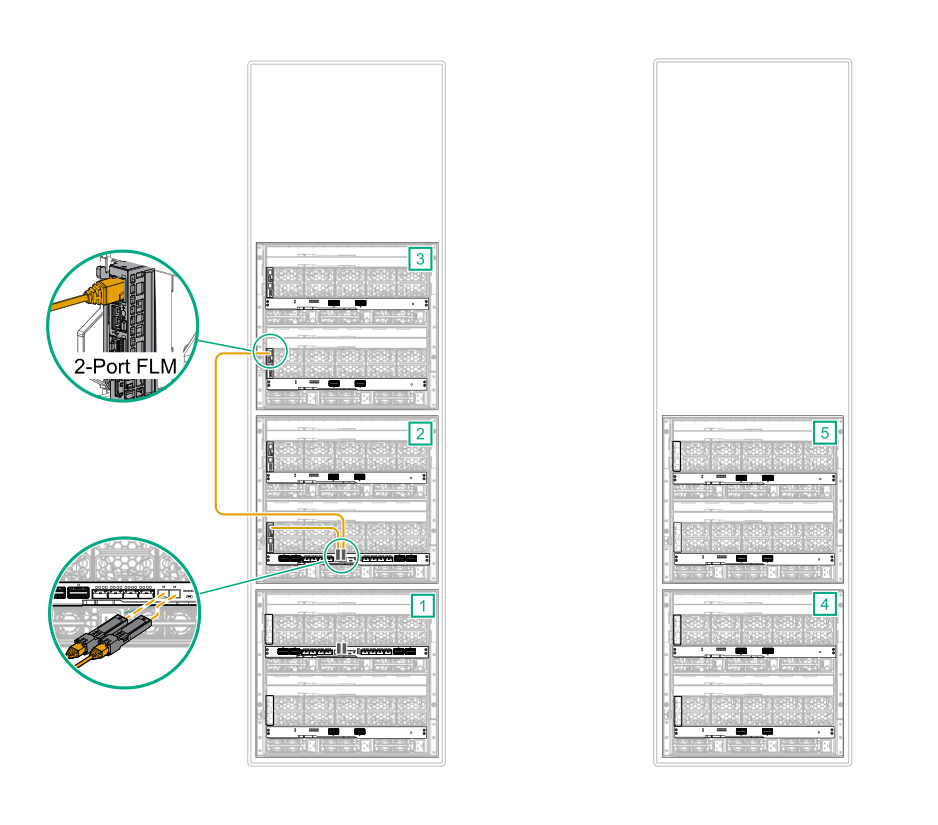
Connect the bay 2 frame link module
MGMT port from each Image Streamer frame to an
10GBase-T SFP+ transceiver.
Connect each
10GBase-T SFP+ transceiver to the X1 and X2 ports on the secondary master ICM in frame 2.
Figure 45: MGMT port to master ICM cabling for a five-frame
HPE Synergy configuration with
HPE Synergy Image Streamer and
4-port FLMs (frame 2)
Master and satellite ICM cabling
Connect an interconnect cable from the L1, L2, L3, and L4 ports on the primary master ICM to each L1 port of the satellite ICM in the same bay.
Figure 46: Primary master ICM to satellite ICM cabling for a five-frame
HPE Synergy configuration with
HPE Synergy Image Streamer and
4-port FLMs
Connect an interconnect cable from the L1, L2, L3, and L4 ports on the secondary master ICM to each L1 port of the satellite ICM in the same bay.
Figure 47: Secondary master ICM to satellite ICM cabling for a five-frame
HPE Synergy configuration with
HPE Synergy Image Streamer and
4-port FLMs
Connect a stacking cable from the first
master ICM to the second
master ICM.
Connect port Q7 on the first
master ICM to port Q7 on the second
master ICM.
Connect port Q8 on the first
master ICM to port Q8 on the second
master ICM.
Figure 48: Stacking cabling for a five-frame
HPE Synergy configuration with
HPE Synergy Image Streamer and
4-port FLMs
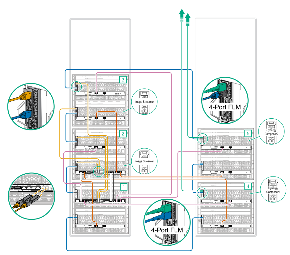
Cabling is complete. The following diagram shows the complete cabling diagram.
Figure 49: Complete cabling for a five-frame
HPE Synergy configuration with
HPE Synergy Image Streamer and
4-port FLMs
 Cabling is complete. The following diagram shows the complete cabling diagram.