Three-frame HPE Synergy Image Streamer configuration cabling example
This cabling example does not cover power or production network cabling.
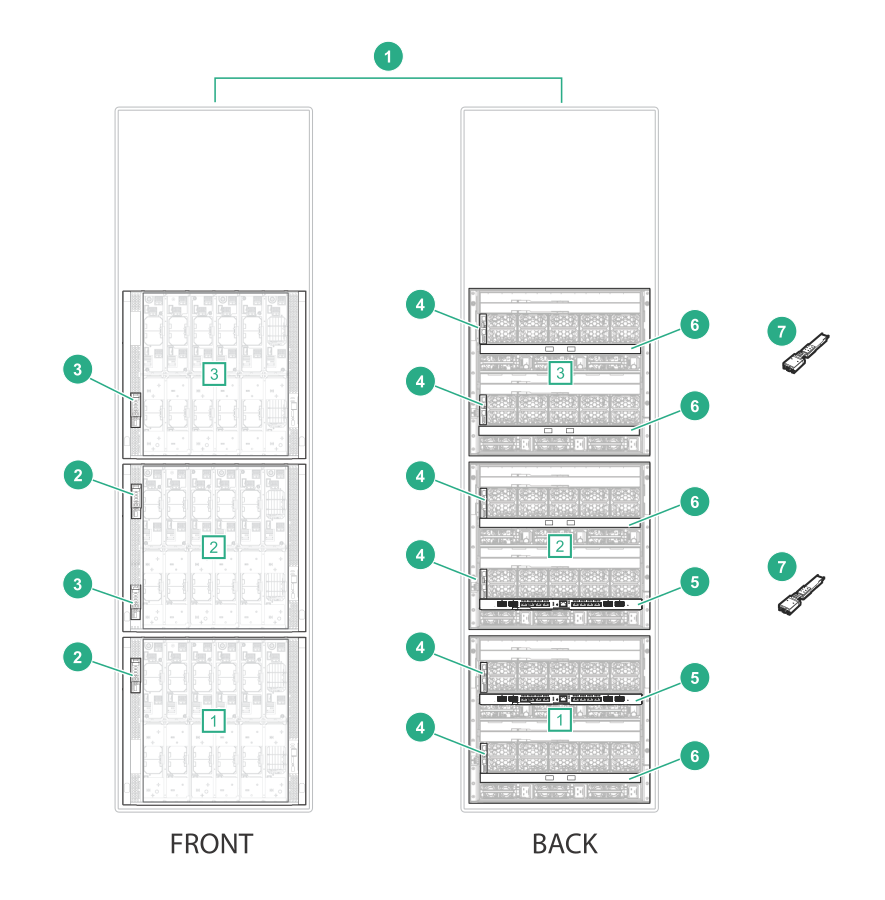
| Item | Description | Quantity |
|---|---|---|
| 1 | HPE Synergy 12000 Frames [1], [2], [3] | 3 |
| 2 | HPE Synergy Composer | 2 |
| 3 | HPE Synergy Image Streamers | 2 |
| 4 | HPE Synergy Frame Link Module | 6 |
| 5 | HPE Synergy Virtual Connect SE 40Gb F8 module (master ICM) | 2 |
| 6 | HPE Synergy 20Gb Interconnect Link Module (satellite ICM) | 4 |
| 7 | HPE Synergy Dual 10GBASE-T QSFP+ 30m RJ45 adapter | 2 |
Management network
-
Connect Ethernet cables from both frame link module
MGMT ports in frame 1 to the management network.
Figure 61: MGMT port to management network cabling for a three-frame HPE Synergy Image Streamer configuration 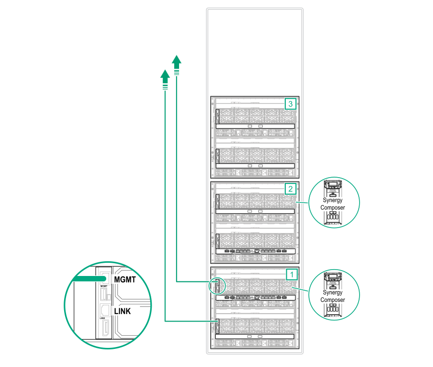
-
Using CAT6A cables, connect all frame link module
LINK ports together.
Figure 62: LINK port cabling for a three-frame HPE Synergy Image Streamer configuration 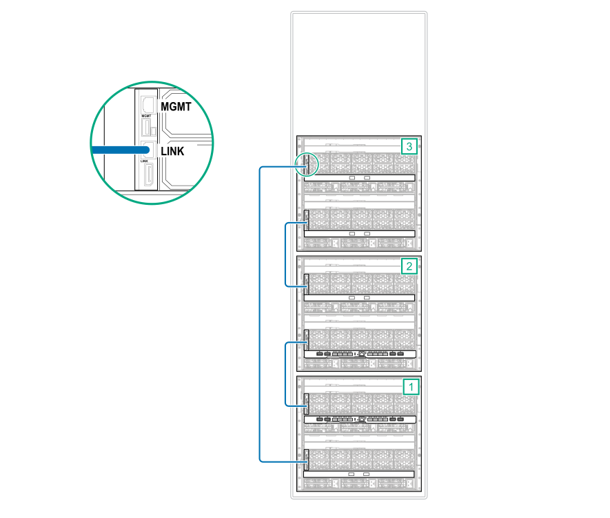
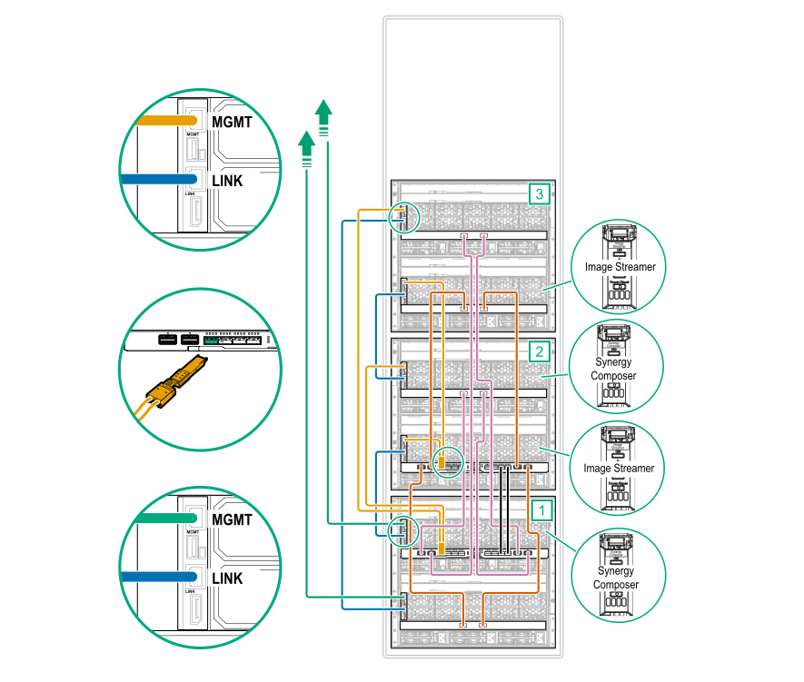
Image Streamer cabling
-
Connect a CAT6A cable from each
MGMT port in the frames with an HPE Image Streamer installed to the master ICMs.
- Connect the bay 1 frame link module
MGMT port from each frame to an
HPE Synergy Dual 10GBASE-T QSFP+ 30m RJ45 adapter.
Connect the HPE Synergy Dual 10GBASE-T QSFP+ 30m RJ45 adapter to the first HPE Synergy Virtual Connect SE 40Gb F8 module.
Figure 63: MGMT port to master ICM cabling for a three-frame HPE Synergy Image Streamer configuration (frame 1) 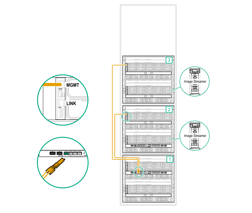
- Connect the bay 2 frame link module
MGMT port from each frame to an
HPE Synergy Dual 10GBASE-T QSFP+ 30m RJ45 adapter.
Connect the HPE Synergy Dual 10GBASE-T QSFP+ 30m RJ45 adapter to the second HPE Synergy Virtual Connect SE 40Gb F8 module.
Figure 64: MGMT port to master ICM cabling for a three-frame HPE Synergy Image Streamer configuration (frame 2) 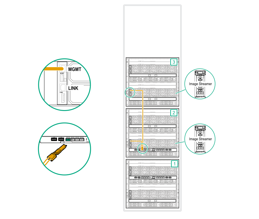
- Connect the bay 1 frame link module
MGMT port from each frame to an
HPE Synergy Dual 10GBASE-T QSFP+ 30m RJ45 adapter.
Master and satellite ICM cabling
-
Connect interconnect cables from ports L1 and L4 on the first
master ICM to the first
satellite ICM.
Connect interconnect cables from ports L2 and L3 on the first master ICM to the second satellite ICM.
Figure 65: Master ICM to satellite ICM cabling for a three-frame HPE Synergy Image Streamer configuration (frame 1) 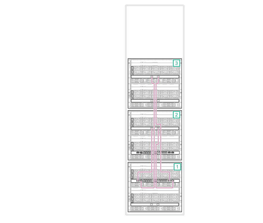
-
Connect interconnect cables from ports L1 and L4 on the second
master ICM to the first
satellite ICM.
Connect interconnect cables from ports L2 and L3 on the second master ICM to the second satellite ICM.
Figure 66: Master ICM to satellite ICM cabling for a three-frame HPE Synergy Image Streamer configuration (frame 2) 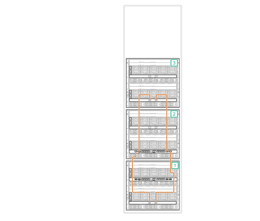
-
Connect a stacking cable from the first
master ICM to the second
master ICM.
- Connect port Q7 on the first master ICM to port Q7 on the second master ICM.
- Connect port Q8 on the first master ICM to port Q8 on the second master ICM.
Figure 67: Master ICM to master ICM stacking cabling for a three-frame HPE Synergy Image Streamer configuration 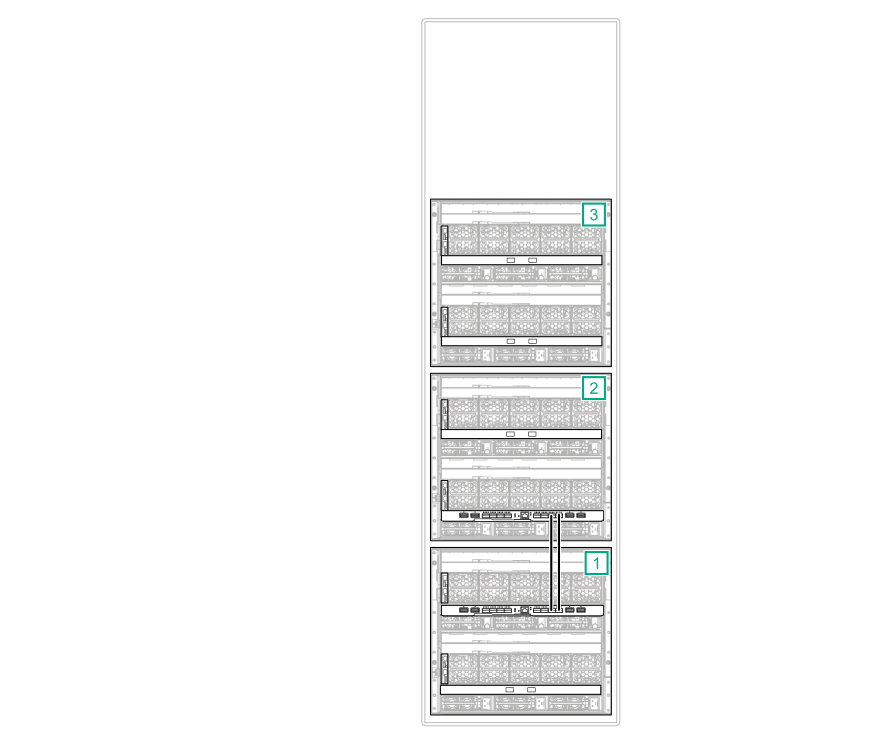
Cabling is complete. The following diagram shows the complete cabling diagram.
Figure 68: Complete cabling for a three-frame HPE Synergy Image Streamer configuration