Add-on two-frame
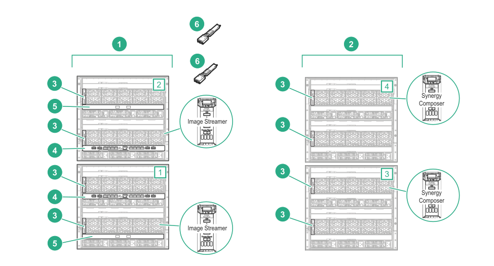
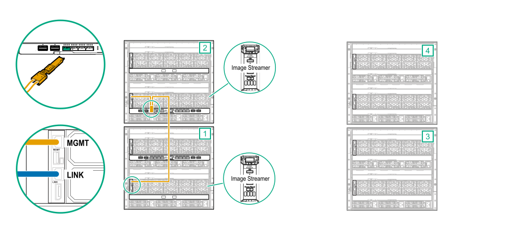
HPE Synergy Image Streamer cabling example
CAUTION:
A two-frame add-on HPE Synergy Image Streamer configuration is only supported if the two HPE Synergy Image Streamer add-on frames are added to an existing HPE Synergy configuration. The existing configuration must have two HPE Synergy Composers installed and two frame link module MGMT ports connected to the management network.
This cabling example shows adding a two-frame HPE Synergy Image Streamer configuration to two existing frames. In this example, the existing frames provide a redundant connection to the management network.
This example does not cover production network cabling or power cabling.
Prerequisites
Figure 52: Components required for a two-frame add-on
HPE Synergy Image Streamer configuration
Item
Description
Quantity
1
HPE Synergy 12000 Frames (add-on frames)
2
2
HPE Synergy 12000 Frames (existing frames)
2
3
HPE Synergy Frame link modules
4
4
HPE Synergy Virtual Connect SE 40Gb F8 module (master ICM)
2
5
HPE Synergy 20Gb Interconnect Link Module
2
6
HPE Synergy Dual 10GBASE-T QSFP+ 30m RJ45 adapter
2
Procedure
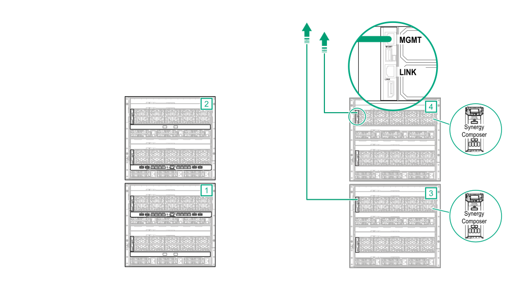
MGMT port cabling
One frame link module MGMT port from each existing frame is connected to the management network for high availability (HA).
CAUTION:
A two-frame add-on HPE Synergy Image Streamer configuration is only supported if the two HPE Synergy Image Streamer add-on frames are added to an existing HPE Synergy configuration. The existing configuration must have two HPE Synergy Composers installed and two frame link module MGMT ports connected to the management network.
Figure 53: MGMT port cabling for a two-frame add-on
HPE Synergy Image Streamer configuration
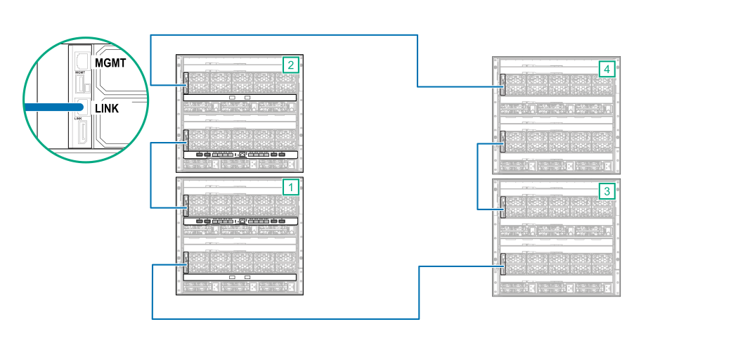
LINK port cabling
Using CAT6A cables, connect the LINK ports between the two add-on HPE Synergy Image Streamer frames and to the existing configuration.
Figure 54: LINK port cabling for a two-frame add-on
HPE Synergy Image Streamer configuration
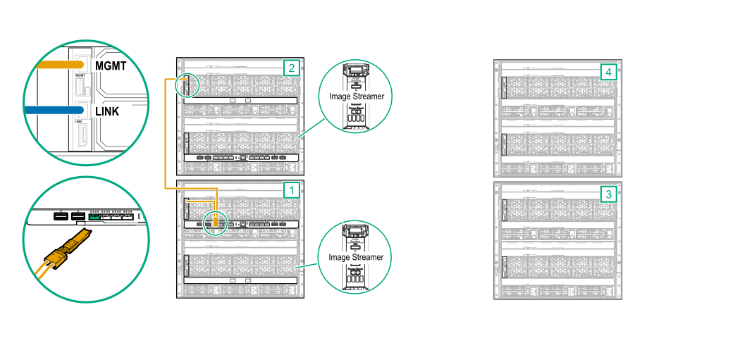
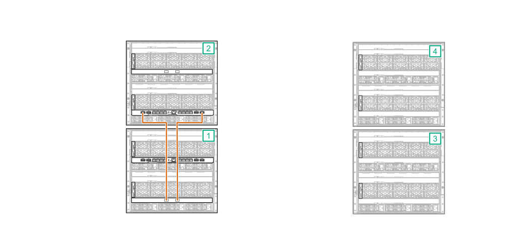
Image Streamer cabling
Connect a CAT6A cable from each MGMT port in the add-on frames to the master ICMs.
Connect the bay 1 frame link module
MGMT port from each add-on frame to an
HPE Synergy Dual 10GBASE-T QSFP+ 30m RJ45 adapter.
Connect the
HPE Synergy Dual 10GBASE-T QSFP+ 30m RJ45 adapter to the first
master ICM.
Figure 55: MGMT port to master ICM cabling for a two-frame add-on
HPE Synergy Image Streamer configuration
Connect the bay 2 frame link module MGMT port from each add-on frame to an
HPE Synergy Dual 10GBASE-T QSFP+ 30m RJ45 adapter.
Connect the
HPE Synergy Dual 10GBASE-T QSFP+ 30m RJ45 adapter to the second
master ICM.
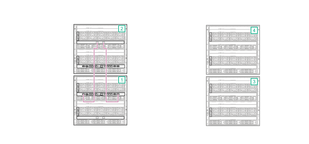
Master and satellite ICM cabling
Connect interconnect cables from ports L1 and L4 on the first
master ICM to the
satellite ICM.
Figure 56: Interconnect cabling for a two-frame add-on
HPE Synergy Image Streamer configuration (frame 1)
Connect interconnect cables from ports L1 and L4 on the second
master ICM to the
satellite ICM.
Figure 57: Interconnect cabling for a two-frame add-on
HPE Synergy Image Streamer configuration (frame 2)
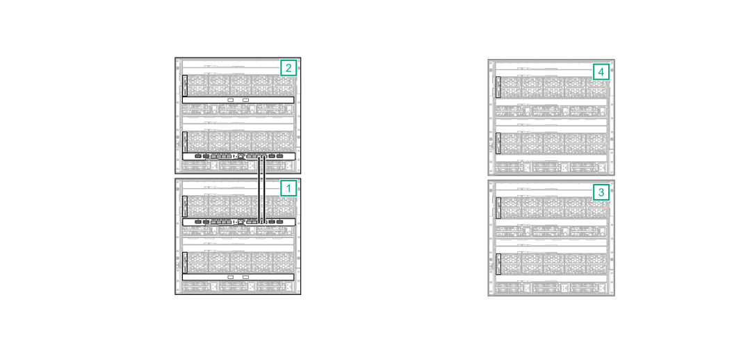
Connect a stacking cable from the first
master ICM to the second
master ICM.
Connect port Q7 on the first
master ICM to port Q7 on the second
master ICM.
Connect port Q8 on the first
master ICM to port Q8 on the second
master ICM.
Figure 58: Master interconnects connected with stacking cables for a two-frame add-on
HPE Synergy Image Streamer configuration
Cabling is complete. The following diagram shows the complete cabling diagram.
Figure 59: Complete cabling for a two-frame add-on
HPE Synergy Image Streamer configuration