Multiframe
4-port FLM cabling example using a fiber optic patch panel
IMPORTANT:
The management network top-of-rack switch must be the same speed as the cables or transceivers used for
MGMT port cabling.
NOTE:
HPE Synergy 4-Port Frame Link Modules require supported SFP+ DAC cables or SFP+ transceivers for cabling. For more information, see the product QuickSpecs on the
Hewlett Packard Enterprise website.
NOTE:
This cabling example does not cover power or production network cabling.
Prerequisites
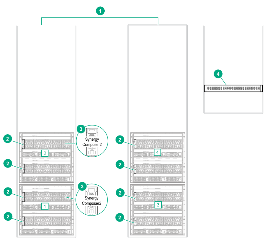
Figure 12: Required components for multiframe
4-port FLM cabling example using a fiber optic patch panel
Item
Description
Amount
1
HPE Synergy 12000 Frames [1], [2], [3], [4]
4
2
HPE Synergy 4-Port Frame Link Modules (4-Port FLM)
Only required in the primary the management ring. Frames in a remote management ring should not have HPE Synergy Composers installed.
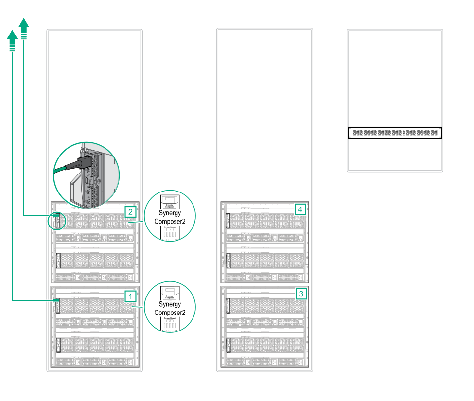
Procedure
Connect DAC cables from two
MGMT ports to the management network.
NOTE: The 4-Port FLM
MGMT port supports
1000BASE-T SFP Transceiver with CAT5 cables,
10GBase-T SFP+ transceiver with CAT6A cables,
SFP DAC cables,
SFP+ 10Gb DAC cables, and
SFP+ 10Gb transceivers with optical cables. For a complete list of cabling options, see the product QuickSpecs
www.hpe.com/info/qs.
NOTE:
The 4-Port FLM
MGMT port supports 1GbE and 10GbE cables and transceivers. The
MGMT port speed is set based on the cables or transceivers used.
Figure 13: MGMT port to management network cabling for multiframe
4-port FLM cabling example using a fiber optic patch panel
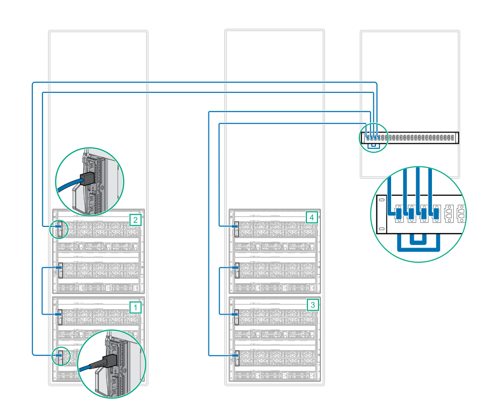
Connect the
LINK ports together.
To cable the
LINK ports of frames in separate racks, use
SFP+ 10Gb transceivers with optical cables connected through the patch panel.
To cable the
LINK ports of frames in the same rack, use
SFP+ 10Gb DAC cables.
Figure 14: LINK port cabling for multiframe
4-port FLM cabling example using a fiber optic patch panel
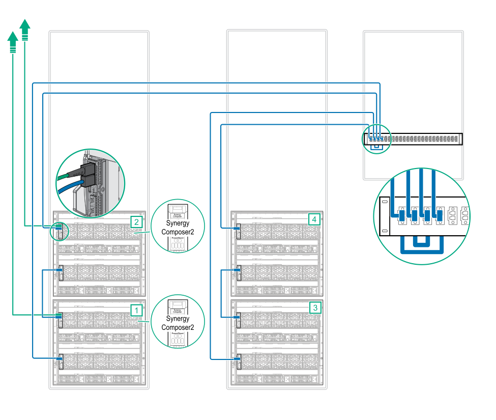
Cabling is complete. The following diagram shows the complete cabling diagram.
Figure 15: Complete cabling for multiframe
4-port FLM cabling example using a fiber optic patch panel