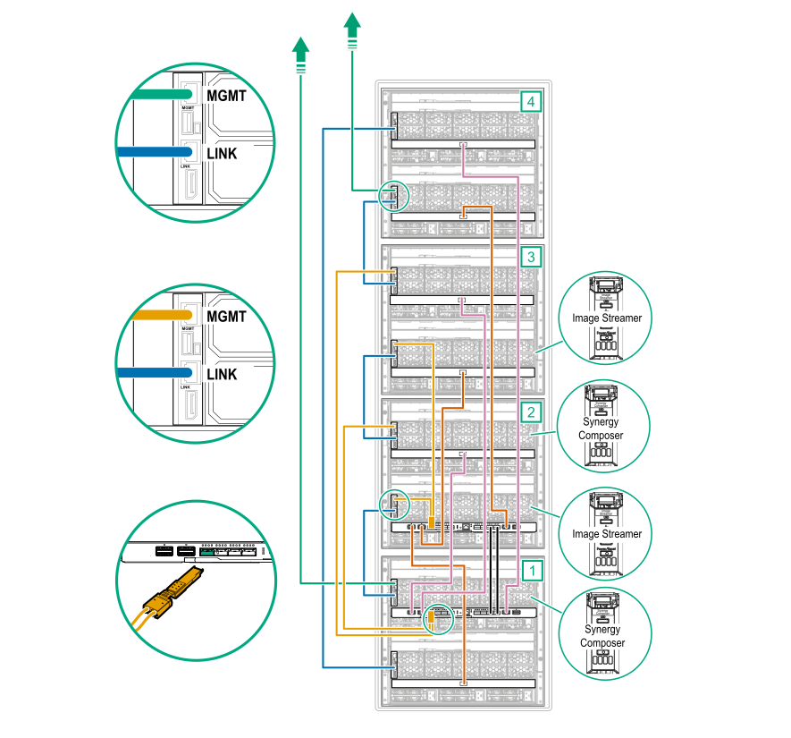
Four-frame HPE Synergy Image Streamer configuration cabling example
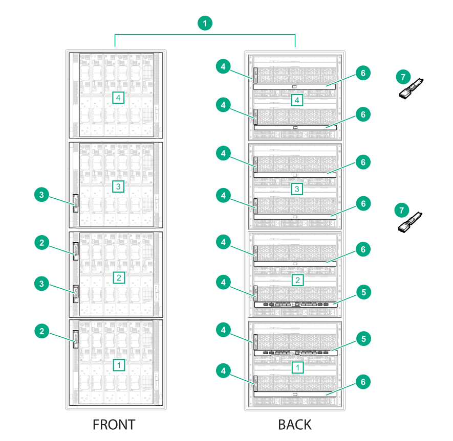
| Item | Description | Quantity |
|---|---|---|
| 1 | HPE Synergy frames [1], [2], [3], [4] | 4 |
| 2 | HPE Synergy Composers | 2 |
| 3 | HPE Synergy Image Streamers | 2 |
| 4 | HPE Synergy Frame Link Module | 8 |
| 5 | HPE Synergy Virtual Connect SE 40Gb F8 module (master ICM) | 2 |
| 6 | HPE Synergy 10Gb Interconnect Link Module (satellite ICM) | 6 |
| 7 | HPE Synergy Dual 10GBASE-T QSFP+ 30m RJ45 adapter | 2 |
NOTE:
This cabling example does not cover power or production network cabling.
Procedure
Management cabling
-
Connect Ethernet cables from two
MGMT ports to the management network.
Figure 70: MGMT ports to management network cabling for a four-frame configuration with Image Streamer 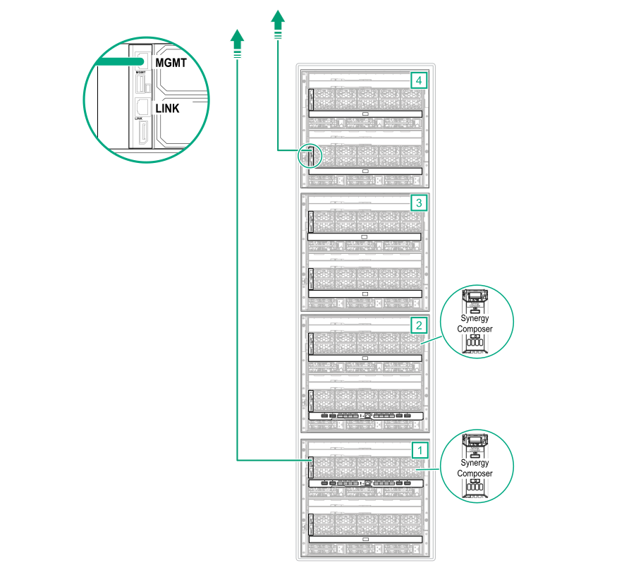
-
Using CAT6A cables, connect all frame link module
LINK ports together.
Figure 71: LINK port cabling for a four-frame configuration with Image Streamer 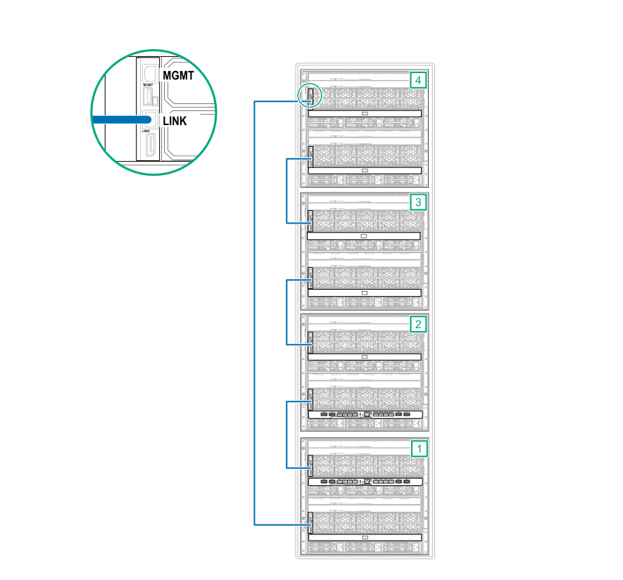
HPE Image Streamer cabling
-
Connect a CAT6A cable from each
MGMT port in the frames with an HPE Image Streamer installed to the master ICMs.
- Connect the bay 1 frame link module
MGMT ports to an
HPE Synergy Dual 10GBASE-T QSFP+ 30m RJ45 adapter.
Connect the HPE Synergy Dual 10GBASE-T QSFP+ 30m RJ45 adapter to the first HPE Synergy Virtual Connect SE 40Gb F8 module.
Figure 72: MGMT port to master ICM cabling for a four-frame configuration with Image Streamer (frame 1) 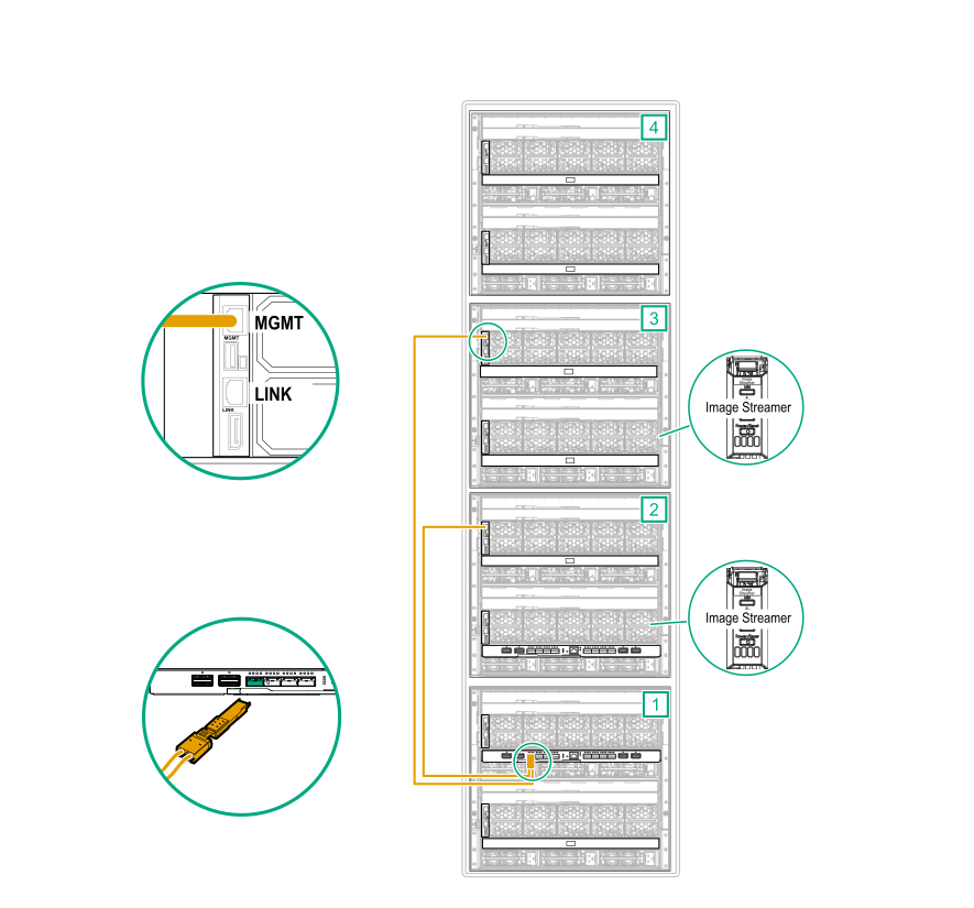
- Connect the bay 2 frame link module
MGMT ports to an
HPE Synergy Dual 10GBASE-T QSFP+ 30m RJ45 adapter.
Connect the HPE Synergy Dual 10GBASE-T QSFP+ 30m RJ45 adapter to the second HPE Synergy Virtual Connect SE 40Gb F8 module.
Figure 73: MGMT port to master ICM cabling for a four-frame configuration with Image Streamer (frame 2) 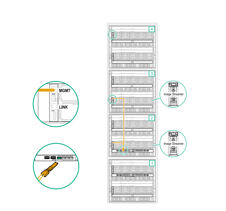
- Connect the bay 1 frame link module
MGMT ports to an
HPE Synergy Dual 10GBASE-T QSFP+ 30m RJ45 adapter.
Master and satellite ICM cabling
-
Connect an interconnect cable from the L1, L2, and L3 ports on the first
master ICM to each
satellite ICM in the same bay.
Figure 74: Master ICM to Satellite ICM cabling for a four-frame configuration with Image Streamer (frame 1) 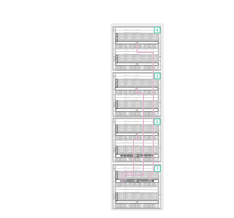
-
Connect an interconnect cable from the L1, L2, and L3 ports on the second
master ICM to each
satellite ICM in the same bay.
Figure 75: Master ICM to Satellite ICM cabling for a four-frame configuration with Image Streamer (frame 2) 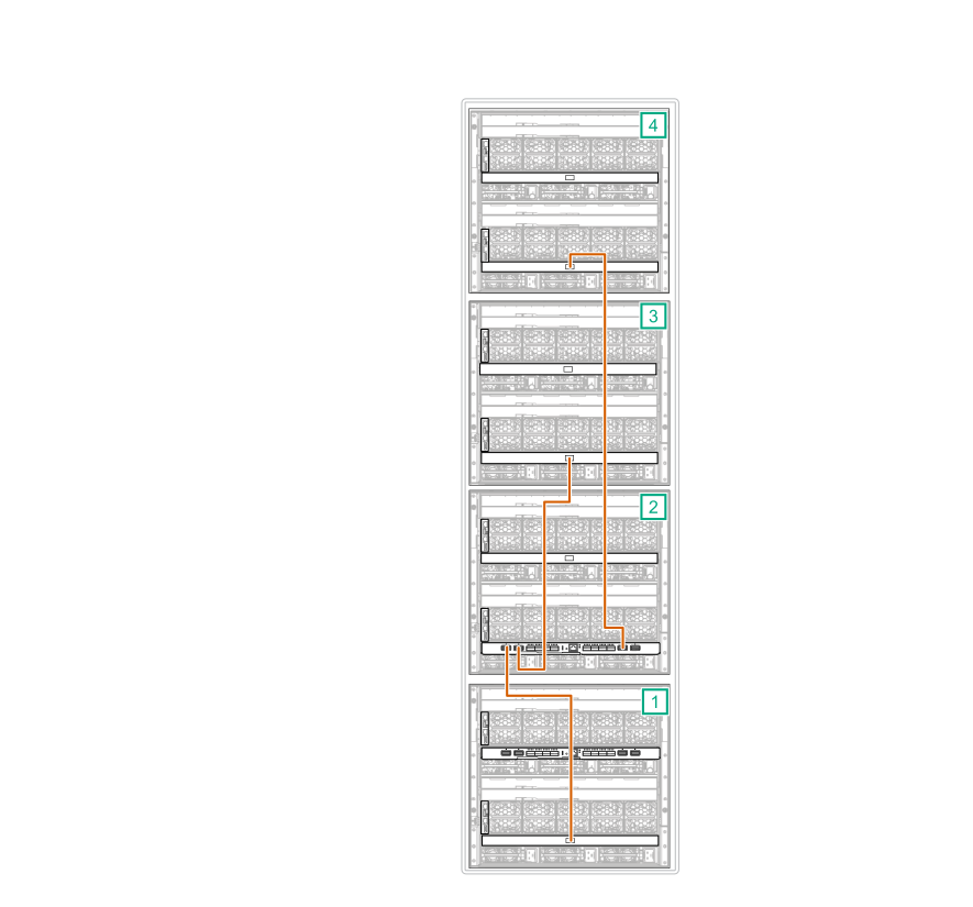
-
Using stacking cables, connect the two master ICMs together.
- Connect port Q7 on the first master ICM to port Q7 on the second master ICM.
- Connect port Q8 on the first master ICM to port Q8 on the second master ICM.
Figure 76: Master interconnect stacking for a four-frame configuration with Image Streamer 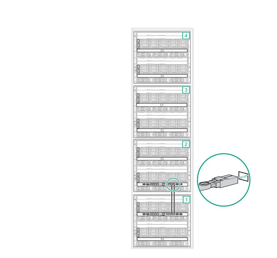
Cabling is complete. The following diagram shows the complete cabling diagram.
Figure 77: Complete cabling for a four-frame configuration with Image Streamer