Multiframe 2-Port FLM cabling example using a CAT6A patch panel
NOTE:
This cabling example does not cover power or production network cabling.
Prerequisites
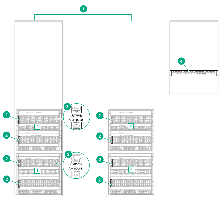
| Item | Description | Amount |
|---|---|---|
| 1 | HPE Synergy 12000 Frames [1], [2], [3], [4] | 4 |
| 2 | HPE Synergy Frame Link Module (2-Port) | 8 |
| 3 | HPE Synergy Composer | 2 |
| 4 | CAT6A patch panel | 1 |
Procedure
-
Connect Ethernet cables from two
MGMT ports to the management network.
Figure 29: MGMT port to management network cabling for two sets of frames with LINK ports cabled through a CAT6A patch panel 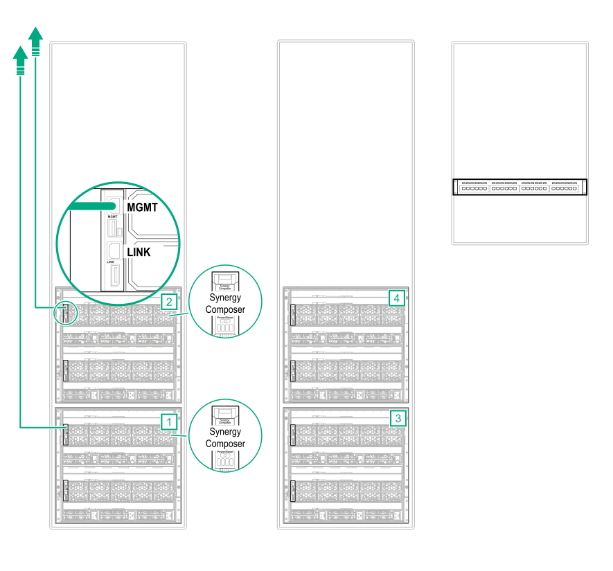
-
Using CAT6A cables, connect the LINK ports together through the CAT6A patch panel.
Figure 30: LINK port cabling for two sets of frames with LINK ports cabled through a CAT6A patch panel 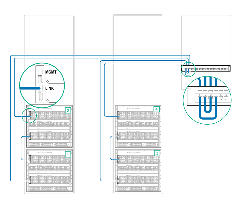
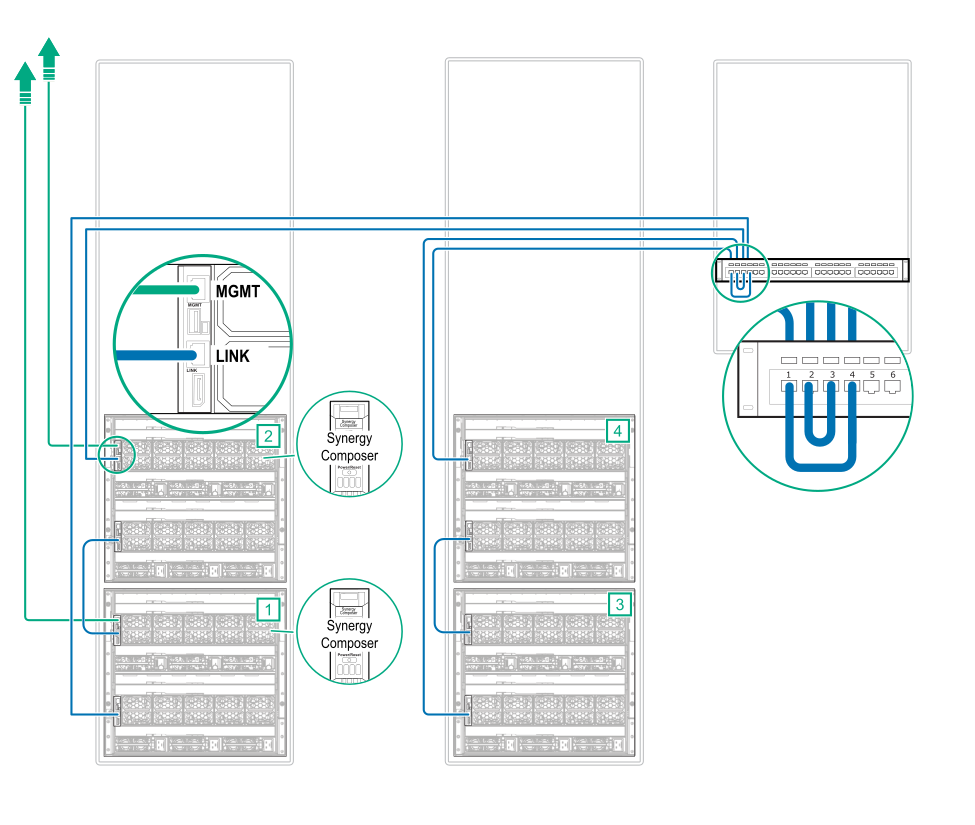
Cabling is complete. The following diagram shows the complete cabling diagram.
Figure 31: Complete cabling for two sets of frames with LINK ports cabled through a CAT6A patch panel