Cabling an HPE Synergy Image Streamer development configuration
A single frame with one HPE Synergy Image Streamer and one HPE Synergy Composer is referred to as a development configuration.
IMPORTANT:
Because this configuration includes only a single Composer and a single Image Streamer,
Hewlett Packard Enterprise does not support this configuration as a production solution. This configuration is intended for development and proof of concept purposes only.
Prerequisites
Installing the Composer in appliance bay 1 and installing Image Streamer in appliance bay 2 is required. The guidelines in this section use this best practice.
This configuration requires initiating the Hardware Setup process. For more information on Hardware Setup, see the
HPE Synergy 12000 Frame Setup and Installation Guide on the HPE Information Library (http://www.hpe.com/info/docs).
This cabling example does not cover power or production network cabling.
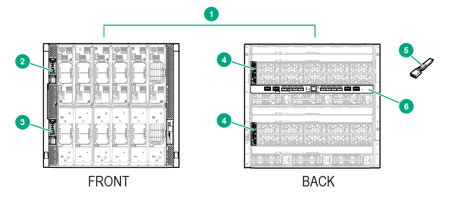
Figure 50: Components required for an HPE Synergy development configuration
Item
Description
Quantity
1
HPE Synergy 12000 frame
1
2
HPE Synergy Composer
1
3
HPE Synergy Image Streamer
1
4
HPE Synergy Frame link module
2
5
HPE Synergy Dual 10GBASE-T QSFP+ 30m RJ45 adapter
1
6
HPE Synergy Virtual Connect SE 40Gb F8 module (master ICM)
1
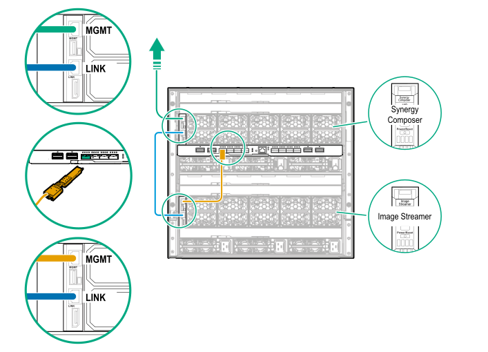
Procedure
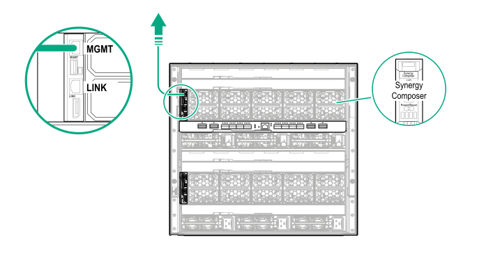
Using an Ethernet cable connect the
MGMT port from the frame link module in bay 1 to the management network.
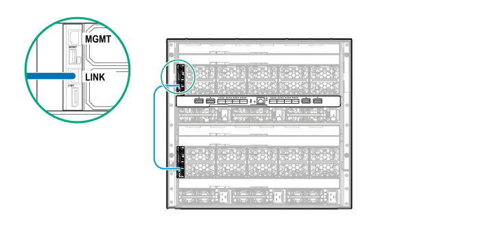
Using a CAT6A cable, connect the
LINK ports of the two installed frame link modules together.
Install the HPE Synergy Image Streamer in front appliance bay 2.
After the frame has been powered and HPE OneView has claimed the
frame, validate that you can make a remote connection to HPE OneView over the management network.
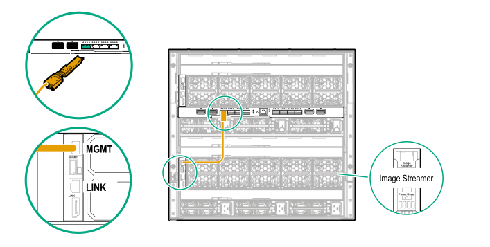
After the management connectivity is validated, connect the
MGMT port of frame link module 2 to a
HPE Synergy Virtual Connect SE 40Gb F8 module installed in the frame.
When a redundant pair of
master ICMs is installed in the frame, connect the
MGMT port of the frame link module in bay 2 to the
master ICM installed in the upper half of the frame (ICM 1, ICM 2, or ICM 3).
To translate from 10GBASE-T to QSFP+, use a dual 10GBASE-T QSFP+ RJ45 transceiver adapter.
In a single frame configuration, one of the two RJ45 jacks of the dual transceiver adapter is not used.
Figure 51: Complete cabling for an HPE Synergy Image Streamer development configuration cabling example