System board
WARNING: To reduce the risk of personal injury from hot surfaces, allow the drives and the internal system components to cool before touching them.
CAUTION: To prevent damage to electrical components, take the appropriate anti-static precautions before beginning any installation, removal, or replacement procedure. Improper grounding can cause electrostatic discharge.
CAUTION: To avoid ESD damage, when removing electrostatic-sensitive components from the failed system board, place the components on a static-dissipating work surface or inside separate antistatic bags.
Procedure
-
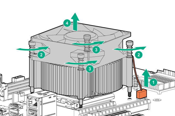
Remove the heatsink:
-
Remove the heatsink from the processor backplate.
CAUTION: The fan does not have a fan guard. Special attention is needed when removing or installing the fan to prevent finger injury.
-
Remove the heatsink from the processor backplate.
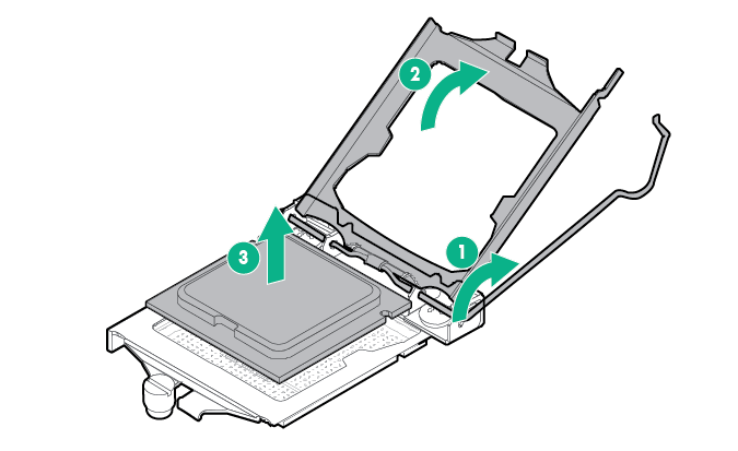
-
Hold the processor by the edges, and then lift it out of the socket.
CAUTION: When returning a damaged system board to Hewlett Packard Enterprise, always install all processor socket covers to prevent damage to the processor sockets and system board. -
Install the processor socket cover on the failed system board.
-
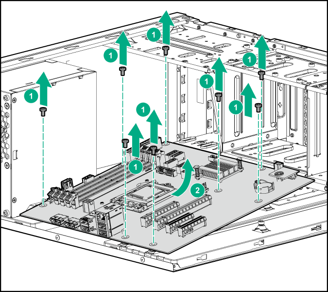
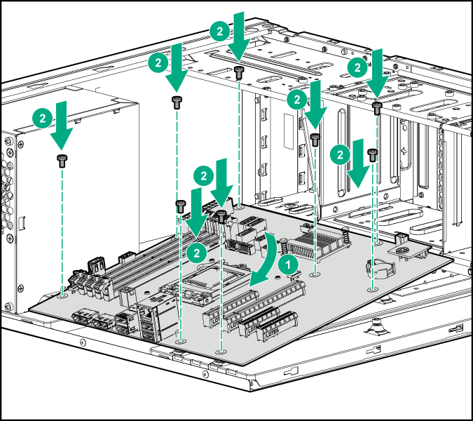
Remove the failed system board.
To replace the system board:
- Install the system board.
- Open the processor locking lever, and then open the processor retaining bracket.
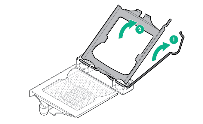
CAUTION: To avoid damage to the processor, do not touch the bottom of the processor, especially the contact area.CAUTION: Failure to completely open the processor locking lever prevents the processor from seating during installation, leading to hardware damage. - Remove the processor socket cover.

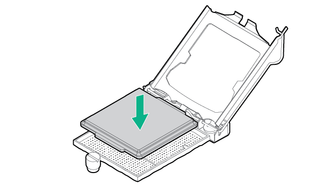
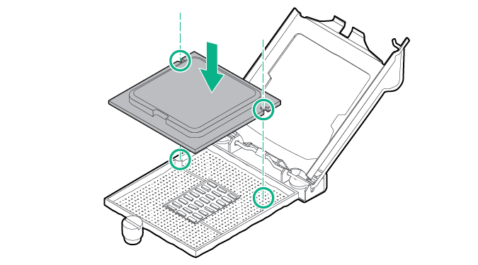
CAUTION: THE PINS ON THE SYSTEM BOARD ARE VERY FRAGILE AND EASILY DAMAGED. To avoid damage to the system board, do not touch the processor or the processor socket contacts. - Install the processor. Use the notches on both sides of the processor to properly align it into the socket.
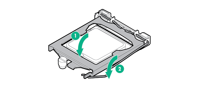
 CAUTION: Be sure to close the processor socket retaining bracket before closing the processor locking lever. The lever should close without resistance. Forcing the lever closed can damage the processor and socket, requiring system board replacement.CAUTION: THE PINS ON THE SYSTEM BOARD ARE VERY FRAGILE AND EASILY DAMAGED. To avoid damage to the system board, do not touch the processor or the processor socket contacts.CAUTION: Do not press down on the processor. Pressing down on the processor might damage the processor socket and the system board. Press only in the area indicated on the processor retaining bracket.
 - Close the processor retaining bracket, and then secure the processor locking lever.
- Clean the old thermal grease from the heatsink and the top of the processor with the alcohol swab. Allow the alcohol to evaporate before continuing.
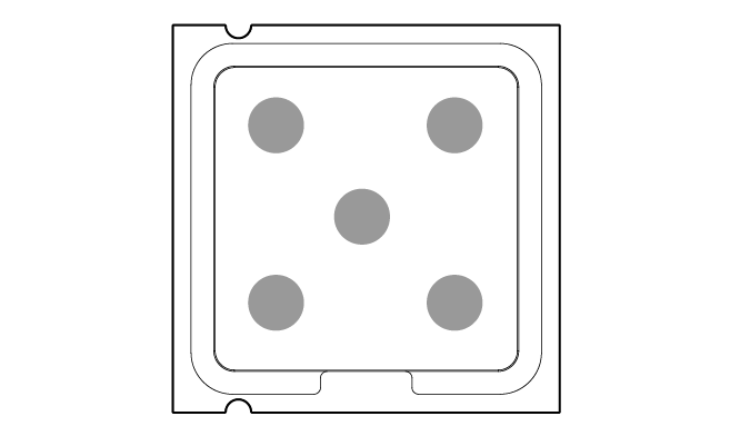
- Apply all the grease to the top of the processor in the following pattern to ensure even distribution.
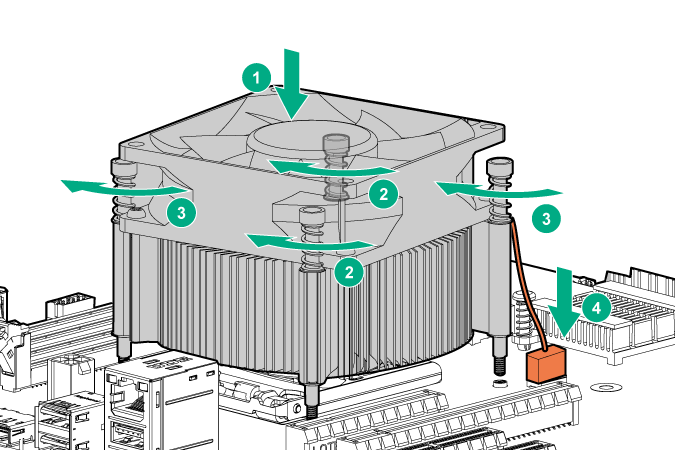
- Install the heatsink:
- Position the heatsink on the processor backplate.
- Tighten one pair of diagonally opposite screws halfway, and then tighten the other pair of screws.
- Finish the installation by completely tightening the screws in the same sequence.
- Connect processor fan cable to system board.
- Install the DIMMs.
- Install all components removed from the failed system board.
- Connect all cables disconnected from the failed system board.
- Install the access panel.
- Connect each power cord to the server.
- Connect each power cord to the power source.
- Power up the
server
IMPORTANT: Install all components with the same configuration that was used on the failed system board.
- Re-enter the server serial number and the product ID.