Example: Configuring BFD for the VRRP master to monitor the uplinks
Network configuration
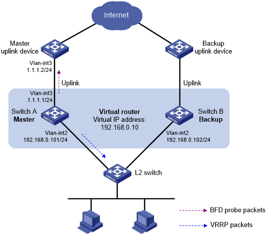
As shown in Figure 60:
Switch A and Switch B belong to VRRP group 1. The virtual IP address of VRRP group 1 is 192.168.0.10.
The default gateway of the hosts in the LAN is 192.168.0.10.
Configure VRRP-Track-BFD collaboration to monitor the uplink on the master and meet the following requirements:
When Switch A operates correctly, the hosts in the LAN access the Internet through Switch A.
When Switch A detects that the uplink is down through BFD, Switch B can preempt as the master. The hosts in the LAN can access the Internet through Switch B.
Figure 60: Network diagram
Procedure
![[IMPORTANT: ]](images/important.png) | IMPORTANT: By default, interfaces on the device are disabled (in ADM or Administratively Down state). To have an interface operate, you must use the undo shutdown command to enable that interface. | |
Create VLANs and assign ports to them. Configure the IP address of each VLAN interface, as shown in Figure 60. (Details not shown.)
Configure Switch A:
# Specify 10.10.10.10 as the source address of BFD echo packets.
<SwitchA> system-view
[SwitchA] bfd echo-source-ip 10.10.10.10
# Create track entry 1 for the BFD session to verify the reachability of the uplink device (1.1.1.2 ).
[SwitchA] track 1 bfd echo interface vlan-interface 3 remote ip 1.1.1.2 local ip 1.1.1.1
# Create VRRP group 1, and specify 192.168.0.10 as the virtual IP address of the group.
[SwitchA] interface vlan-interface 2
[SwitchA-Vlan-interface2] vrrp vrid 1 virtual-ip 192.168.0.10
# Set the priority of Switch A to 110 in VRRP group 1.
[SwitchA-Vlan-interface2] vrrp vrid 1 priority 110
# Associate VRRP group 1 with track entry 1 and decrease the router priority by 20 when the state of track entry 1 changes to negative.
[SwitchA-Vlan-interface2] vrrp vrid 1 track 1 priority reduced 20
[SwitchA-Vlan-interface2] return
On Switch B, create VRRP group 1, and specify 192.168.0.10 as the virtual IP address of the group.
<SwitchB> system-view
[SwitchB] interface vlan-interface 2
[SwitchB-Vlan-interface2] vrrp vrid 1 virtual-ip 192.168.0.10
[SwitchB-Vlan-interface2] return
Verifying the configuration
# Display detailed information about the VRRP group on Switch A.
<SwitchA> display vrrp verbose
IPv4 Virtual Router Information:
 Running Mode      : Standard
 Total number of virtual routers : 1
   Interface Vlan-interface2
     VRID             : 1               Adver Timer  : 100
     Admin Status     : Up              State        : Master
     Config Pri       : 110             Running Pri  : 110
     Preempt Mode     : Yes             Delay Time   : 0
     Auth Type        : None
     Virtual IP       : 192.168.0.10
     Virtual MAC      : 0000-5e00-0101
     Master IP        : 192.168.0.101
   VRRP Track Information:
     Track Object   : 1              State : Positive          Pri Reduced : 20
# Display information about track entry 1 on Switch A.
<SwitchA> display track 1
Track ID: 1
  State: Positive
  Duration: 0 days 0 hours 0 minutes 32 seconds
  Notification delay: Positive 0, Negative 0 (in seconds)
  Tracked object:
    BFD session mode: Echo
    Outgoing interface: Vlan-interface2
    VPN instance name: --
    Remote IP: 1.1.1.2
    Local IP: 1.1.1.1
# Display detailed information about the VRRP group on Switch B.
<SwitchB> display vrrp verbose
IPv4 Virtual Router Information:
 Running Mode      : Standard
 Total number of virtual routers : 1
   Interface Vlan-interface2
     VRID             : 1               Adver Timer  : 100
     Admin Status     : Up              State        : Backup
     Config Pri       : 100             Running Pri  : 100
     Preempt Mode     : Yes             Delay Time   : 0
     Become Master    : 2200ms left
     Auth Type        : None
     Virtual IP       : 192.168.0.10
     Master IP        : 192.168.0.101
The output shows that when the status of track entry 1 becomes Positive, Switch A is the master and Switch B is the backup.
# Display information about track entry 1 when the uplink of Switch A goes down.
<SwitchA> display track 1
Track ID: 1
  State: Negative
  Duration: 0 days 0 hours 0 minutes 32 seconds
  Notification delay: Positive 0, Negative 0 (in seconds)
  Tracked object:
    BFD session mode: Echo
    Outgoing interface: Vlan-interface2
    VPN instance name: --
    Remote IP: 1.1.1.2
    Local IP: 1.1.1.1
# Display detailed information about VRRP group 1 on Switch A.
<SwitchA> display vrrp verbose
IPv4 Virtual Router Information:
 Running Mode      : Standard
 Total number of virtual routers : 1
   Interface Vlan-interface2
     VRID             : 1               Adver Timer  : 100
     Admin Status     : Up              State        : Backup
     Config Pri       : 110             Running Pri  : 90
     Preempt Mode     : Yes             Delay Time   : 0
     Become Master    : 2200ms left
     Auth Type        : None
     Virtual IP       : 192.168.0.10
     Master IP        : 192.168.0.102
   VRRP Track Information:
     Track Object   : 1              State : Negative          Pri Reduced : 20
# Display detailed information about VRRP group 1 on Switch B.
<SwitchB> display vrrp verbose
IPv4 Virtual Router Information:
 Running Mode      : Standard
 Total number of virtual routers : 1
   Interface Vlan-interface2
     VRID             : 1               Adver Timer  : 100
     Admin Status     : Up              State        : Master
     Config Pri       : 100             Running Pri  : 100
     Preempt Mode     : Yes             Delay Time   : 0
     Auth Type        : None
     Virtual IP       : 192.168.0.10
     Virtual MAC      : 0000-5e00-0101
     Master IP        : 192.168.0.102
The output shows that when Switch A detects that the uplink fails through BFD, it decreases its priority by 20. Switch B then preempts as the master.