Example: Configuring static routing-Track-NQA collaboration
Network configuration
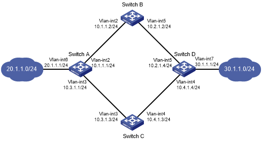
As shown in Figure 61:
Switch A is the default gateway of the hosts in network 20.1.1.0/24.
Switch D is the default gateway of the hosts in network 30.1.1.0/24.
Hosts in the two networks communicate with each other through static routes.
To ensure network availability, configure route backup and static routing-Track-NQA collaboration on Switch A and Switch D as follows:
On Switch A, assign a higher priority to the static route to 30.1.1.0/24 with next hop Switch B. This route is the master route. The static route to 30.1.1.0/24 with next hop Switch C acts as the backup route. When the master route is unavailable, the backup route takes effect. Switch A forwards packets to 30.1.1.0/24 through Switch C.
On Switch D, assign a higher priority to the static route to 20.1.1.0/24 with next hop Switch B. This route is the master route. The static route to 20.1.1.0/24 with next hop Switch C acts as the backup route. When the master route is unavailable, the backup route takes effect. Switch D forwards packets to 20.1.1.0/24 through Switch C.
Figure 61: Network diagram
Procedure
![[IMPORTANT: ]](images/important.png) | IMPORTANT: By default, interfaces on the device are disabled (in ADM or Administratively Down state). To have an interface operate, you must use the undo shutdown command to enable that interface. | |
Create VLANs and assign ports to them. Configure the IP address of each VLAN interface, as shown in Figure 61. (Details not shown.)
Configure Switch A:
# Configure a static route to 30.1.1.0/24 with next hop 10.1.1.2 and the default priority (60). Associate this static route with track entry 1.
<SwitchA> system-view
[SwitchA] ip route-static 30.1.1.0 24 10.1.1.2 track 1
# Configure a static route to 30.1.1.0/24 with next hop 10.3.1.3 and priority 80.
[SwitchA] ip route-static 30.1.1.0 24 10.3.1.3 preference 80
# Configure a static route to 10.2.1.4 with next hop 10.1.1.2.
[SwitchA] ip route-static 10.2.1.4 24 10.1.1.2
# Create an NQA operation with administrator name admin and operation tag test.
[SwitchA] nqa entry admin test
# Specify the ICMP echo operation type.
[SwitchA-nqa-admin-test] type icmp-echo
# Specify 10.2.1.4 as the destination address of the operation.
[SwitchA-nqa-admin-test-icmp-echo] destination ip 10.2.1.4
# Specify 10.1.1.2 as the next hop of the operation.
[SwitchA-nqa-admin-test-icmp-echo] next-hop ip 10.1.1.2
# Configure the ICMP echo operation to repeat every 100 milliseconds.
[SwitchA-nqa-admin-test-icmp-echo] frequency 100
# Configure reaction entry 1, specifying that five consecutive probe failures trigger the Track module.
[SwitchA-nqa-admin-test-icmp-echo] reaction 1 checked-element probe-fail threshold-type consecutive 5 action-type trigger-only
[SwitchA-nqa-admin-test-icmp-echo] quit
# Start the NQA operation.
[SwitchA] nqa schedule admin test start-time now lifetime forever
# Configure track entry 1, and associate it with reaction entry 1 of the NQA operation.
[SwitchA] track 1 nqa entry admin test reaction 1
Configure Switch B:
# Configure a static route to 30.1.1.0/24 with next hop 10.2.1.4.
<SwitchB> system-view
[SwitchB] ip route-static 30.1.1.0 24 10.2.1.4
# Configure a static route to 20.1.1.0/24 with next hop 10.1.1.1.
[SwitchB] ip route-static 20.1.1.0 24 10.1.1.1
Configure Switch C:
# Configure a static route to 30.1.1.0/24 with next hop 10.4.1.4.
<SwitchC> system-view
[SwitchC] ip route-static 30.1.1.0 24 10.4.1.4
# Configure a static route to 20.1.1.0/24 with next hop 10.3.1.1.
[SwitchC] ip route-static 20.1.1.0 24 10.3.1.1
Configure Switch D:
# Configure a static route to 20.1.1.0/24 with next hop 10.2.1.2 and the default priority (60). Associate this static route with track entry 1.
<SwitchD> system-view
[SwitchD] ip route-static 20.1.1.0 24 10.2.1.2 track 1
# Configure a static route to 20.1.1.0/24 with next hop 10.4.1.3 and priority 80.
[SwitchD] ip route-static 20.1.1.0 24 10.4.1.3 preference 80
# Configure a static route to 10.1.1.1 with next hop 10.2.1.2.
[SwitchD] ip route-static 10.1.1.1 24 10.2.1.2
# Create an NQA operation with administrator name admin and operation tag test.
[SwitchD] nqa entry admin test
# Specify the ICMP echo operation type.
[SwitchD-nqa-admin-test] type icmp-echo
# Specify 10.1.1.1 as the destination address of the operation.
[SwitchD-nqa-admin-test-icmp-echo] destination ip 10.1.1.1
# Specify 10.2.1.2 as the next hop of the operation.
[SwitchD-nqa-admin-test-icmp-echo] next-hop ip 10.2.1.2
# Configure the ICMP echo operation to repeat every 100 milliseconds.
[SwitchD-nqa-admin-test-icmp-echo] frequency 100
# Configure reaction entry 1, specifying that five consecutive probe failures trigger the Track module.
[SwitchD-nqa-admin-test-icmp-echo] reaction 1 checked-element probe-fail threshold-type consecutive 5 action-type trigger-only
[SwitchD-nqa-admin-test-icmp-echo] quit
# Start the NQA operation.
[SwitchD] nqa schedule admin test start-time now lifetime forever
# Configure track entry 1, and associate it with reaction entry 1 of the NQA operation.
[SwitchD] track 1 nqa entry admin test reaction 1
Verifying the configuration
# Display information about the track entry on Switch A.
[SwitchA] display track all
Track ID: 1
  State: Positive
  Duration: 0 days 0 hours 0 minutes 32 seconds
  Notification delay: Positive 0, Negative 0 (in seconds)
  Tracked object:
    NQA entry: admin test
    Reaction: 1
    Remote IP/URL:--
    Local IP:--
    Interface:--
The output shows that the status of the track entry is Positive, indicating that the NQA operation has succeeded and the master route is available.
# Display the routing table of Switch A.
[SwitchA] display ip routing-table

Destinations : 10       Routes : 10

Destination/Mask    Proto  Pre  Cost         NextHop         Interface
10.1.1.0/24         Direct 0    0            10.1.1.1        Vlan2
10.1.1.1/32         Direct 0    0            127.0.0.1       InLoop0
10.2.1.0/24         Static 60   0            10.1.1.2        Vlan2
10.3.1.0/24         Direct 0    0            10.3.1.1        Vlan3
10.3.1.1/32         Direct 0    0            127.0.0.1       InLoop0
20.1.1.0/24         Direct 0    0            20.1.1.1        Vlan6
20.1.1.1/32         Direct 0    0            127.0.0.1       InLoop0
30.1.1.0/24         Static 60   0            10.1.1.2        Vlan2
127.0.0.0/8         Direct 0    0            127.0.0.1       InLoop0
127.0.0.1/32        Direct 0    0            127.0.0.1       InLoop0
The output shows that Switch A forwards packets to 30.1.1.0/24 through Switch B.
# Remove the IP address of interface VLAN-interface 2 on Switch B.
<SwitchB> system-view
[SwitchB] interface vlan-interface 2
[SwitchB-Vlan-interface2] undo ip address
# Display information about the track entry on Switch A.
[SwitchA] display track all
Track ID: 1
  State: Negative
  Duration: 0 days 0 hours 0 minutes 32 seconds
  Notification delay: Positive 0, Negative 0 (in seconds)
  Tracked object:
    NQA entry: admin test
    Reaction: 1
    Remote IP/URL:--
    Local IP:--
    Interface:--
The output shows that the status of the track entry is Negative, indicating that the NQA operation has failed and the master route is unavailable.
# Display the routing table of Switch A.
[SwitchA] display ip routing-table

Destinations : 10       Routes : 10

Destination/Mask    Proto  Pre  Cost         NextHop         Interface
10.1.1.0/24         Direct 0    0            10.1.1.1        Vlan2
10.1.1.1/32         Direct 0    0            127.0.0.1       InLoop0
10.2.1.0/24         Static 60   0            10.1.1.2        Vlan2
10.3.1.0/24         Direct 0    0            10.3.1.1        Vlan3
10.3.1.1/32         Direct 0    0            127.0.0.1       InLoop0
20.1.1.0/24         Direct 0    0            20.1.1.1        Vlan6
20.1.1.1/32         Direct 0    0            127.0.0.1       InLoop0
30.1.1.0/24         Static 80   0            10.3.1.3        Vlan3
127.0.0.0/8         Direct 0    0            127.0.0.1       InLoop0
127.0.0.1/32        Direct 0    0            127.0.0.1       InLoop0
The output shows that Switch A forwards packets to 30.1.1.0/24 through Switch C. The backup static route has taken effect.
# Verify that hosts in 20.1.1.0/24 can communicate with the hosts in 30.1.1.0/24 when the master route fails.
[SwitchA] ping -a 20.1.1.1 30.1.1.1
Ping 30.1.1.1: 56  data bytes, press CTRL_C to break
Reply from 30.1.1.1: bytes=56 Sequence=1 ttl=254 time=2 ms
Reply from 30.1.1.1: bytes=56 Sequence=2 ttl=254 time=1 ms
Reply from 30.1.1.1: bytes=56 Sequence=3 ttl=254 time=1 ms
Reply from 30.1.1.1: bytes=56 Sequence=4 ttl=254 time=2 ms
Reply from 30.1.1.1: bytes=56 Sequence=5 ttl=254 time=1 ms

--- Ping statistics for 30.1.1.1 ---
5 packet(s) transmitted, 5 packet(s) received, 0.00% packet loss
round-trip min/avg/max/std-dev = 1/1/2/1 ms
# Verify that the hosts in 30.1.1.0/24 can communicate with the hosts in 20.1.1.0/24 when the master route fails.
[SwitchB] ping -a 30.1.1.1 20.1.1.1
Ping 20.1.1.1: 56  data bytes, press CTRL_C to break
Reply from 20.1.1.1: bytes=56 Sequence=1 ttl=254 time=2 ms
Reply from 20.1.1.1: bytes=56 Sequence=2 ttl=254 time=1 ms
Reply from 20.1.1.1: bytes=56 Sequence=3 ttl=254 time=1 ms
Reply from 20.1.1.1: bytes=56 Sequence=4 ttl=254 time=1 ms
Reply from 20.1.1.1: bytes=56 Sequence=5 ttl=254 time=1 ms

--- Ping statistics for 20.1.1.1 ---
5 packet(s) transmitted, 5 packet(s) received, 0.00% packet loss
round-trip min/avg/max/std-dev = 1/1/2/1 ms