Example: Configuring BFD for a VRRP backup to monitor the master
Network configuration
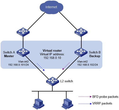
As shown in Figure 59:
Switch A and Switch B belong to VRRP group 1. The virtual IP address of VRRP group 1 is 192.168.0.10.
The default gateway of the hosts in the LAN is 192.168.0.10.
Configure VRRP-Track-BFD collaboration to monitor the master on the backup and meet the following requirements:
When Switch A operates correctly, the hosts in the LAN access the Internet through Switch A.
When Switch A fails, the backup (Switch B) can detect the state change of the master through BFD and become the new master. The hosts in the LAN access the Internet through Switch B.
Figure 59: Network diagram
Procedure
![[IMPORTANT: ]](images/important.png) | IMPORTANT: By default, interfaces on the device are disabled (in ADM or Administratively Down state). To have an interface operate, you must use the undo shutdown command to enable that interface. | |
Create VLANs and assign ports to them. Configure the IP address of each VLAN interface, as shown in Figure 59. (Details not shown.)
Configure Switch A:
# Create VRRP group 1, and configure virtual IP address 192.168.0.10 for the group.
<SwitchA> system-view
[SwitchA] interface vlan-interface 2
[SwitchA-Vlan-interface2] vrrp vrid 1 virtual-ip 192.168.0.10
# Set the priority of Switch A to 110 in VRRP group 1.
[SwitchA-Vlan-interface2] vrrp vrid 1 priority 110
[SwitchA-Vlan-interface2] return
Configure Switch B:
# Specify 10.10.10.10 as the source address of BFD echo packets.
<SwitchB> system-view
[SwitchB] bfd echo-source-ip 10.10.10.10
# Create track entry 1, and associate it with the BFD session to verify the reachability of Switch A.
[SwitchB] track 1 bfd echo interface vlan-interface 2 remote ip 192.168.0.101 local ip 192.168.0.102
# Create VRRP group 1, and configure virtual IP address 192.168.0.10 for the group.
[SwitchB] interface vlan-interface 2
[SwitchB-Vlan-interface2] vrrp vrid 1 virtual-ip 192.168.0.10
# Configure VRRP group 1 to monitor the status of track entry 1.
[SwitchB-Vlan-interface2] vrrp vrid 1 track 1 switchover
[SwitchB-Vlan-interface2] return
Verifying the configuration
# Display detailed information about VRRP group 1 on Switch A.
<SwitchA> display vrrp verbose
IPv4 Virtual Router Information:
 Running Mode      : Standard
 Total number of virtual routers : 1
   Interface Vlan-interface2
     VRID             : 1               Adver Timer  : 100
     Admin Status     : Up              State        : Master
     Config Pri       : 110             Running Pri  : 110
     Preempt Mode     : Yes             Delay Time   : 0
     Auth Type        : None
     Virtual IP       : 192.168.0.10
     Virtual MAC      : 0000-5e00-0101
     Master IP        : 192.168.0.101
# Display detailed information about VRRP group 1 on Switch B.
<SwitchB> display vrrp verbose
IPv4 Virtual Router Information:
 Running Mode      : Standard
 Total number of virtual routers : 1
   Interface Vlan-interface2
     VRID             : 1               Adver Timer  : 100
     Admin Status     : Up              State        : Backup
     Config Pri       : 100             Running Pri  : 100
     Preempt Mode     : Yes             Delay Time   : 0
     Become Master    : 2200ms left
     Auth Type        : None
     Virtual IP       : 192.168.0.10
     Master IP        : 192.168.0.101
   VRRP Track Information:
     Track Object   : 1              State : Positive          Switchover
# Display information about track entry 1 on Switch B.
<SwitchB> display track 1
Track ID: 1
  State: Positive
  Duration: 0 days 0 hours 0 minutes 32 seconds
  Notification delay: Positive 0, Negative 0 (in seconds)
  Tracked object:
    BFD session mode: Echo
    Outgoing interface: Vlan-interface2
    VPN instance name: --
    Remote IP: 192.168.0.101
    Local IP: 192.168.0.102
The output shows that when the status of the track entry becomes Positive, Switch A is the master and Switch B is the backup.
# Enable VRRP state debugging and BFD event notification debugging on Switch B.
<SwitchB> terminal debugging
<SwitchB> terminal monitor
<SwitchB> debugging vrrp fsm
<SwitchB> debugging bfd ntfy
# When Switch A fails, the following output is displayed on Switch B.
*Dec 17 14:44:34:142 2008 SwitchB BFD/7/DEBUG: Notify application:TRACK State:DOWN
*Dec 17 14:44:34:144 2008 SwitchB VRRP4/7/FSM:
 IPv4 Vlan-interface2 | Virtual Router 1 : Backup --> Master   reason: The status of the tracked object changed
# Display detailed information about the VRRP group on Switch B.
<SwitchB> display vrrp verbose
IPv4 Virtual Router Information:
 Running Mode      : Standard
 Total number of virtual routers : 1
   Interface Vlan-interface2
     VRID             : 1               Adver Timer  : 100
     Admin Status     : Up              State        : Master
     Config Pri       : 100             Running Pri  : 100
     Preempt Mode     : Yes             Delay Time   : 0
     Auth Type        : None
     Virtual IP       : 192.168.0.10
     Virtual MAC      : 0000-5e00-0101
     Master IP        : 192.168.0.102
   VRRP Track Information:
     Track Object   : 1              State : Negative          Switchover
The output shows that when BFD detects that Switch A fails, the Track module notifies VRRP to change the status of Switch B to master. The backup can quickly preempt as the master without waiting for a period three times the advertisement interval plus the Skew_Time.