Example: Configuring VRRP-Track-NQA collaboration
Network configuration
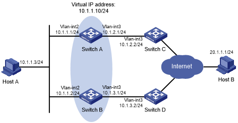
As shown in Figure 58:
Host A requires access to Host B. The default gateway of Host A is 10.1.1.10/24.
Switch A and Switch B belong to VRRP group 1. The virtual IP address of VRRP group 1 is 10.1.1.10.
Configure VRRP-Track-NQA collaboration to monitor the uplink on the master and meet the following requirements:
When Switch A operates correctly, Switch A forwards packets from Host A to Host B.
When NQA detects a fault on the uplink of Switch A, Switch B forwards packets from Host A to Host B.
Figure 58: Network diagram
Procedure
![[IMPORTANT: ]](images/important.png) | IMPORTANT: By default, interfaces on the device are disabled (in ADM or Administratively Down state). To have an interface operate, you must use the undo shutdown command to enable that interface. | |
Create VLANs and assign ports to them. Configure the IP address of each VLAN interface, as shown in Figure 58. (Details not shown.)
Configure an NQA operation on Switch A:
# Create an NQA operation with administrator name admin and operation tag test.
<SwitchA> system-view
[SwitchA] nqa entry admin test
# Specify the ICMP echo operation type.
[SwitchA-nqa-admin-test] type icmp-echo
# Specify 10.1.2.2 as the destination address of ICMP echo requests.
[SwitchA-nqa-admin-test-icmp-echo] destination ip 10.1.2.2
# Configure the ICMP echo operation to repeat every 100 milliseconds.
[SwitchA-nqa-admin-test-icmp-echo] frequency 100
# Configure reaction entry 1, specifying that five consecutive probe failures trigger the Track module.
[SwitchA-nqa-admin-test-icmp-echo] reaction 1 checked-element probe-fail threshold-type consecutive 5 action-type trigger-only
[SwitchA-nqa-admin-test-icmp-echo] quit
# Start the NQA operation.
[SwitchA] nqa schedule admin test start-time now lifetime forever
On Switch A, configure track entry 1, and associate it with reaction entry 1 of the NQA operation.
[SwitchA] track 1 nqa entry admin test reaction 1
Configure VRRP on Switch A:
# Specify VRRPv2 to run on VLAN-interface 2.
[SwitchA] interface vlan-interface 2
[SwitchA-Vlan-interface2] vrrp version 2
# Create VRRP group 1, and configure virtual IP address 10.1.1.10 for the group.
[SwitchA-Vlan-interface2] vrrp vrid 1 virtual-ip 10.1.1.10
# Set the priority of Switch A to 110 in VRRP group 1.
[SwitchA-Vlan-interface2] vrrp vrid 1 priority 110
# Set the authentication mode of VRRP group 1 to simple, and the authentication key to hello.
[SwitchA-Vlan-interface2] vrrp vrid 1 authentication-mode simple hello
# Configure the master to send VRRP packets every 500 centiseconds.
[SwitchA-Vlan-interface2] vrrp vrid 1 timer advertise 500
# Configure Switch A to operate in preemptive mode and set the preemption delay to 5000 centiseconds.
[SwitchA-Vlan-interface2] vrrp vrid 1 preempt-mode timer delay 5000
# Associate VRRP group 1 with track entry 1 and decrease the router priority by 30 when the state of track entry 1 changes to negative.
[SwitchA-Vlan-interface2] vrrp vrid 1 track 1 priority reduced 30
Configure VRRP on Switch B:
# Specify VRRPv2 to run on VLAN-interface 2.
<SwitchB> system-view
[SwitchB] interface vlan-interface 2
[SwitchB-Vlan-interface2] vrrp version 2
# Create VRRP group 1, and configure virtual IP address 10.1.1.10 for the group.
[SwitchB-Vlan-interface2] vrrp vrid 1 virtual-ip 10.1.1.10
# Set the authentication mode of VRRP group 1 to simple, and the authentication key to hello.
[SwitchB-Vlan-interface2] vrrp vrid 1 authentication-mode simple hello
# Configure the master to send VRRP packets every 500 centiseconds.
[SwitchB-Vlan-interface2] vrrp vrid 1 timer advertise 500
# Configure Switch B to operate in preemptive mode and set the preemption delay to 5000 centiseconds.
[SwitchB-Vlan-interface2] vrrp vrid 1 preempt-mode timer delay 5000
Verifying the configuration
# Ping Host B from Host A to verify that Host B is reachable. (Details not shown.)
# Display detailed information about VRRP group 1 on Switch A.
[SwitchA-Vlan-interface2] display vrrp verbose
IPv4 Virtual Router Information:
 Running Mode      : Standard
 Total number of virtual routers : 1
   Interface Vlan-interface2
     VRID             : 1               Adver Timer  : 500
     Admin Status     : Up              State        : Master
     Config Pri       : 110             Running Pri  : 110
     Preempt Mode     : Yes             Delay Time   : 5000
     Auth Type        : Simple          Key          : ******
     Virtual IP       : 10.1.1.10
     Virtual MAC      : 0000-5e00-0101
     Master IP        : 10.1.1.1
   VRRP Track Information:
     Track Object   : 1              State : Positive          Pri Reduced : 30
# Display detailed information about VRRP group 1 on Switch B.
[SwitchB-Vlan-interface2] display vrrp verbose
IPv4 Virtual Router Information:
 Running Mode      : Standard
 Total number of virtual routers : 1
   Interface Vlan-interface2
     VRID             : 1               Adver Timer  : 500
     Admin Status     : Up              State        : Backup
     Config Pri       : 100             Running Pri  : 100
     Preempt Mode     : Yes             Delay Time   : 5000
     Become Master    : 2200ms left
     Auth Type        : Simple          Key          : ******
     Virtual IP       : 10.1.1.10
     Master IP        : 10.1.1.1
The output shows that in VRRP group 1, Switch A is the master, and Switch B is a backup. Switch A forwards packets from Host A to Host B.
# Disconnect the link between Switch A and Switch C, and verify that Host A can still ping Host B. (Details not shown.)
# Display detailed information about VRRP group 1 on Switch A.
[SwitchA-Vlan-interface2] display vrrp verbose
IPv4 Virtual Router Information:
 Running Mode      : Standard
 Total number of virtual routers : 1
   Interface Vlan-interface2
     VRID             : 1               Adver Timer  : 500
     Admin Status     : Up              State        : Backup
     Config Pri       : 110             Running Pri  : 80
     Preempt Mode     : Yes             Delay Time   : 5000
     Become Master    : 2200ms left
     Auth Type        : Simple          Key          : ******
     Virtual IP       : 10.1.1.10
     Master IP        : 10.1.1.2
   VRRP Track Information:
     Track Object   : 1              State : Negative          Pri Reduced : 30
# Display detailed information about VRRP group 1 on Switch B.
[SwitchB-Vlan-interface2] display vrrp verbose
IPv4 Virtual Router Information:
 Running Mode      : Standard
 Total number of virtual routers : 1
   Interface Vlan-interface2
     VRID             : 1               Adver Timer  : 500
     Admin Status     : Up              State        : Master
     Config Pri       : 100             Running Pri  : 100
     Preempt Mode     : Yes             Delay Time   : 5000
     Auth Type        : Simple          Key          : ******
     Virtual IP       : 10.1.1.10
     Virtual MAC      : 0000-5e00-0101
     Master IP        : 10.1.1.2
The output shows that Switch A becomes the backup, and Switch B becomes the master. Switch B forwards packets from Host A to Host B.