Installation procedures
![[IMPORTANT: ]](images/important.png) | IMPORTANT: Allow 0.8 m (2.62 ft) of clearance around the switch for heat dissipation. | |
To install the switch:
Hold the two sides of the switch and steadily move the switch to the workbench.
Lift the switch a little higher than the workbench and put it on the workbench.
(Optional.) Install the cable management brackets on both sides of the switch and fasten the screws, as shown in Figure 21.
![[NOTE: ]](images/note.png)
NOTE:
The circled areas in Figure 21 are the cable management bracket installation holes.
A 12508E or 12518E switch has one column of installation holes.
Figure 21: Installing cable management brackets on both sides of the switch
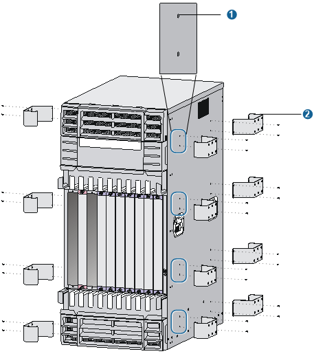
(1) Installation holes | (2) Cable management brackets |
Secure the L-shaped bracket to the switch.
Move the switch to make sure holes in the L-shaped bracket align with wall anchor holes in the ground.
Insert the anchor bolts in the holes, and use a wrench to fasten the bolts.
Figure 22: Installing L-shaped brackets
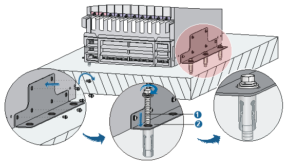
(1) Anchor bolt | (2) L-shaped bracket |