Dynamic BGP peer configuration example
Network requirements
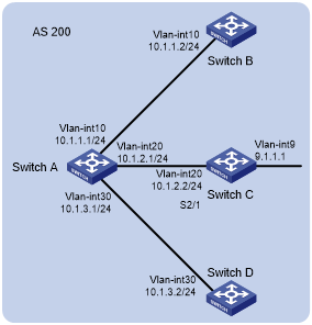
As shown in Figure 80, Switch A needs to establish IBGP peer relationships with Switch B, Switch C, and Switch D in network 10.1.0.0/16. Configure dynamic BGP peers to simplify the configuration.
Configure Switch A as the route reflector, and configure Switch B, Switch C, and Switch D as its clients.
Figure 80: Network diagram
Configuration procedure
Configure IP addresses for interfaces. (Details not shown.)
Configure IBGP peer relationship:
# Configure Switch A to establish dynamic BGP peer relationships with switches in network 10.1.0.0/16.
<SwitchA> system-view
[SwitchA] bgp 200
[SwitchA-bgp-default] router-id 1.1.1.1
[SwitchA-bgp-default] peer 10.1.0.0 16 as-number 200
[SwitchA-bgp-default] address-family ipv4
[SwitchA-bgp-default-ipv4] peer 10.1.0.0 16 enable
# Configure Switch B to establish an IBGP peer relationship with Switch A.
<SwitchB> system-view
[SwitchB] bgp 200
[SwitchB-bgp-default] router-id 2.2.2.2
[SwitchB-bgp-default] peer 10.1.1.1 as-number 200
[SwitchB-bgp-default] address-family ipv4
[SwitchB-bgp-default-ipv4] peer 10.1.1.1 enable
# Configure Switch C to establish an IBGP peer relationship with Switch A.
<SwitchC> system-view
[SwitchC] bgp 200
[SwitchC-bgp-default] router-id 3.3.3.3
[SwitchC-bgp-default] peer 10.1.2.1 as-number 200
[SwitchC-bgp-default] address-family ipv4
[SwitchC-bgp-default-ipv4] peer 10.1.2.1 enable
# Configure Switch D to establish an IBGP peer relationship with Switch A.
<SwitchD> system-view
[SwitchD] bgp 200
[SwitchD-bgp-default] router-id 4.4.4.4
[SwitchD-bgp-default] peer 10.1.3.1 as-number 200
[SwitchD-bgp-default] address-family ipv4
[SwitchD-bgp-default-ipv4] peer 10.1.3.1 enable
# Display BGP peer information on Switch A. The output shows that Switch A has established IBGP peer relationships with Switch B, Switch C, and Switch D.
[SwitchA] display bgp peer ipv4

 BGP local router ID : 1.1.1.1
 Local AS number : 200

 Total number of peers : 3                 Peers in established state : 3

 * - Dynamically created peer
  Peer                    AS  MsgRcvd  MsgSent OutQ PrefRcv Up/Down  State

 *10.1.1.2               200        7       10    0       0 00:06:09 Established
 *10.1.2.2               200        7       10    0       0 00:06:09 Established
 *10.1.3.2               200        7       10    0       0 00:06:09 Established
Configure Switch A as the route reflector, and configure peers in network 10.1.0.0/16 as its clients.
[SwitchA-bgp-default-ipv4] peer 10.1.0.0 16 reflect-client
Configure Switch C to advertise network 9.1.1.0/24.
[SwitchC-bgp-default-ipv4] network 9.1.1.0 24
Verifying the configuration
# Verify that route 9.1.1.0/24 exists in the BGP routing table on Switch A, Switch B, and Switch D. This example uses Switch A.
[SwitchA-bgp-default] display bgp routing-table ipv4

 Total Number of Routes: 1

 BGP Local router ID is 1.1.1.1
 Status codes: * - valid, > - best, d - dampened, h - history,
               s - suppressed, S - stale, i - internal, e - external
               Origin: i - IGP, e - EGP, ? - incomplete

     Network            NextHop         MED        LocPrf     PrefVal Path/Ogn

  * i 9.1.1.0/24        10.1.2.2        0          100        0       ?