BGP LS configuration example
Network requirements
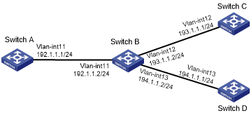
As shown in Figure 81, all switches run BGP. Run IBGP between Switch A and Switch B, between Switch B and Switch C, and between Switch B and Switch D.
Configure Switch B as a route reflector with client Switch A to allow Switch A to learn LS information advertised by Switch C and Switch D.
Figure 81: Network diagram
Configuration procedure
Configure IP addresses for interfaces and configure OSPF on Switch C and Switch D. (Details not shown.)
Configure BGP connections:
# Configure Switch A.
<SwitchA> system-view
[SwitchA] bgp 100
[SwitchA-bgp-default] peer 192.1.1.2 as-number 100
[SwitchA-bgp-default] address-family link-state
[SwitchA-bgp-default-ls] peer 192.1.1.2 enable
[SwitchA-bgp-default-ls] quit
[SwitchA-bgp-default] quit
# Configure Switch B.
<SwitchB> system-view
[SwitchB] bgp 100
[SwitchB-bgp-default] peer 192.1.1.1 as-number 100
[SwitchB-bgp-default] peer 193.1.1.1 as-number 100
[SwitchB-bgp-default] peer 194.1.1.1 as-number 100
[SwitchB-bgp-default] address-family link-state
[SwitchB-bgp-default-ls] peer 192.1.1.1 enable
[SwitchB-bgp-default-ls] peer 193.1.1.1 enable
[SwitchB-bgp-default-ls] peer 194.1.1.1 enable
[SwitchB-bgp-default-ls] quit
[SwitchB-bgp-default] quit
# Configure Switch C.
<SwitchC> system-view
[SwitchC] bgp 100
[SwitchC-bgp-default] peer 193.1.1.2 as-number 100
[SwitchC-bgp-default] address-family link-state
[SwitchC-bgp-default-ls] peer 193.1.1.2 enable
[SwitchC-bgp-default-ls] quit
[SwitchC-bgp-default] quit
[SwitchC] ospf
[SwitchC-ospf-1] distribute bgp-ls
[SwitchC-ospf-1] area 0
[SwitchC-ospf-1-area-0.0.0.0] network 0.0.0.0 0.0.0.0
[SwitchC-ospf-1-area-0.0.0.0] quit
[SwitchC-ospf-1] quit
# Configure Switch D.
<SwitchD> system-view
[SwitchD] bgp 100
[SwitchD-bgp-default] peer 194.1.1.2 as-number 100
[SwitchD-bgp-default] address-family link-state
[SwitchD-bgp-default-ls] peer 194.1.1.2 enable
[SwitchD-bgp-default-ls] quit
[SwitchD-bgp-default] quit
[SwitchD] ospf
[SwitchD-ospf-1] distribute bgp-ls
[SwitchD-ospf-1] area 0
[SwitchD-ospf-1-area-0.0.0.0] network 0.0.0.0 0.0.0.0
[SwitchD-ospf-1-area-0.0.0.0] quit
[SwitchD-ospf-1] quit
Configure Switch B as the route reflector.
[SwitchB] bgp 100
[SwitchB-bgp-default] address-family link-state
[SwitchB-bgp-default-ls] peer 192.1.1.1 reflect-client
[SwitchB-bgp-default-ls] quit
[SwitchB-bgp-default] quit
Verifying the configuration
# Verify that Switch A has learned LS information advertised by Switch C and Switch D.
[SwitchA] display bgp link-state
 Total number of routes: 4
 BGP local Switch ID is 192.1.1.1
 Status codes: * - valid, > - best, d - dampened, h - history,
               s - suppressed, S - stale, i - internal, e - external
               Origin: i - IGP, e - EGP, ? - incomplete
 Prefix codes: E link, V node, T IP reacheable route, u/U unknown,
               I Identifier, N local node, R remote node, L link, P prefix,
               L1/L2 ISIS level-1/level-2, O OSPF, D direct, S static,
               a area-ID, , l link-ID, t topology-ID, s ISO-ID,
               c confed-ID/ASN, b bgp-identifier, r Switch-ID,
               i if-address, n nbr-address, o OSPF Route-type, p IP-prefix
               d designated Switch address
i Network : [V][O][I0x0][N[c100][b193.1.1.1][a0.0.0.0][r193.1.1.1]]/376
    NextHop : 193.1.1.1                                LocPrf    : 100
    PrefVal : 0                                        OutLabel  : NULL
    MED     :
    Path/Ogn: i
i Network : [V][O][I0x0][N[c100][b194.1.1.1][a0.0.0.0][r194.1.1.1]]/376
    NextHop : 194.1.1.1                                LocPrf    : 100
    PrefVal : 0                                        OutLabel  : NULL
    MED     :
    Path/Ogn: i
i Network : [T][O][I0x0][N[c100][b193.1.1.1][a0.0.0.0][r193.1.1.1]][P[o0x1][p193.1.1.0/24]]/480
    NextHop : 193.1.1.1                                LocPrf    : 100
    PrefVal : 0                                        OutLabel  : NULL
    MED     :
    Path/Ogn: i
i Network : [T][O][I0x0][N[c100][b194.1.1.1][a0.0.0.0][r194.1.1.1]][P[o0x1][p194.1.1.0/24]]/480
    NextHop : 194.1.1.1                                LocPrf    : 100
    PrefVal : 0                                        OutLabel  : NULL
    MED     :
    Path/Ogn: i