Multicast BGP configuration example
Network requirements
As shown in Figure 79, OSPF runs within AS 100 and AS 200 to ensure intra-AS connectivity. MBGP runs between the two ASs to exchange IPv4 unicast routes used for RPF check.
Configure the Loopback 0 interface of Switch A and Switch B as the C-BSR and C-RP.
Configure Switch A and Switch B to establish a Multicast Source Discovery Protocol (MSDP) peer relationship through MBGP, so that the receiver can receive multicast traffic from the source.
Figure 79: Network diagram
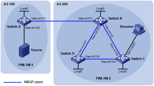
Table 20: Interface and IP address assignment
Device | Interface | IP address | Device | Interface | IP address |
|---|---|---|---|---|---|
Source | N/A | 10.110.1.100/24 | Switch C | Vlan-int200 | 10.110.2.1/24 |
Switch A | Vlan-int100 | 10.110.1.1/24 | Vlan-int102 | 192.168.2.2/24 | |
Vlan-int101 | 192.168.1.1/24 | Vlan-int104 | 192.168.4.1/24 | ||
Loop0 | 1.1.1.1/32 | Loop0 | 3.3.3.3/32 | ||
Switch B | Vlan-int101 | 192.168.1.2/24 | Switch D | Vlan-int103 | 192.168.3.2/24 |
Vlan-int102 | 192.168.2.1/24 | Vlan-int104 | 192.168.4.2/24 | ||
Vlan-int103 | 192.168.3.1/24 | Loop0 | 4.4.4.4/32 | ||
Loop0 | 2.2.2.2/32 |
Configuration procedure
Configure IP addresses for interfaces and configure OSPF (this example uses OSPF process 1) in AS 200 to ensure intra-AS connectivity. (Details not shown.)
Enable IP multicast routing, PIM-SM, and IGMP, and configure BSR boundaries:
# On Switch A, enable multicast routing globally, and enable PIM-SM on interfaces.
<SwitchA> system-view
[SwitchA] multicast routing
[SwitchA-mrib] quit
[SwitchA] interface vlan-interface 100
[SwitchA-Vlan-interface100] pim sm
[SwitchA-Vlan-interface100] quit
[SwitchA] interface vlan-interface 101
[SwitchA-Vlan-interface101] pim sm
[SwitchA-Vlan-interface101] quit
# Configure Switch B and Switch D in the same way that Switch A was configured.
# On Switch C, enable multicast routing globally.
<SwitchC> system-view
[SwitchC] multicast routing
[SwitchA-mrib] quit
# Enable PIM-SM on interfaces, and enable IGMP on VLAN-interface 200.
[SwitchC] interface vlan-interface 102
[SwitchC-Vlan-interface102] pim sm
[SwitchC-Vlan-interface102] quit
[SwitchC] interface vlan-interface 104
[SwitchC-Vlan-interface104] pim sm
[SwitchC-Vlan-interface104] quit
[SwitchC] interface vlan-interface 200
[SwitchC-Vlan-interface200] pim sm
[SwitchC-Vlan-interface200] igmp enable
[SwitchC-Vlan-interface200] quit
# Configure the BSR boundary on Switch A.
[SwitchA] interface vlan-interface 101
[SwitchA-Vlan-interface101] pim bsr-boundary
[SwitchA-Vlan-interface101] quit
# Configure the BSR boundary on Switch B.
[SwitchB] interface vlan-interface 101
[SwitchB-Vlan-interface101] pim bsr-boundary
[SwitchB-Vlan-interface101] quit
Configure Loopback 0, C-BSR, and C-RP:
# Configure the Loopback 0 interface and specify it as the C-BSR and C-RP on Switch A.
[SwitchA] interface loopback 0
[SwitchA-LoopBack0] ip address 1.1.1.1 32
[SwitchA-LoopBack0] pim sm
[SwitchA-LoopBack0] quit
[SwitchA] pim
[SwitchA-pim] c-bsr 1.1.1.1
[SwitchA-pim] c-rp 1.1.1.1
[SwitchA-pim] quit
# Configure the Loopback 0 interface and specify it as the C-BSR and C-RP on Switch B.
[SwitchB] interface loopback 0
[SwitchB-LoopBack0] ip address 2.2.2.2 32
[SwitchB-LoopBack0] pim sm
[SwitchB-LoopBack0] quit
[SwitchB] pim
[SwitchB-pim] c-bsr 2.2.2.2
[SwitchB-pim] c-rp 2.2.2.2
[SwitchB-pim] quit
Configure BGP to establish BGP IPv4 multicast peers and redistribute routes:
# On Switch A, establish an EBGP session to Switch B.
[SwitchA] bgp 100
[SwitchA-bgp-default] router-id 1.1.1.1
[SwitchA-bgp-default] peer 192.168.1.2 as-number 200
# Enable exchange of IPv4 unicast routes used for RPF check with Switch B.
[SwitchA-bgp-default] address-family ipv4 multicast
[SwitchA-bgp-default-mul-ipv4] peer 192.168.1.2 enable
# Redistribute direct routes into BGP.
[SwitchA-bgp-default-mul-ipv4] import-route direct
[SwitchA-bgp-default-mul-ipv4] quit
[SwitchA-bgp-default] quit
# On Switch B, establish an EBGP session to Switch A.
[SwitchB] bgp 200
[SwitchB-bgp-default] router-id 2.2.2.2
[SwitchB-bgp-default] peer 192.168.1.1 as-number 100
# Enable exchange of IPv4 unicast routes used for RPF check with Switch B.
[SwitchB-bgp-default] address-family ipv4 multicast
[SwitchB-bgp-default-mul-ipv4] peer 192.168.1.1 enable
# Redistribute OSPF routes into BGP.
[SwitchB-bgp-default-mul-ipv4] import-route ospf 1
[SwitchB-bgp-default-mul-ipv4] quit
[SwitchB-bgp-default] quit
Configure MSDP peers:
# Configure an MSDP peer on Switch A.
[SwitchA] msdp
[SwitchA-msdp] peer 192.168.1.2 connect-interface vlan-interface 101
[SwitchA-msdp] quit
# Configure an MSDP peer on Switch B.
[SwitchB] msdp
[SwitchB-msdp] peer 192.168.1.1 connect-interface vlan-interface 101
[SwitchB-msdp] quit
Verifying the configuration
# Verify the BGP IPv4 multicast peer information on Switch B.
[SwitchB] display bgp peer ipv4 multicast

 BGP local router ID : 2.2.2.2
 Local AS number : 200
 Total number of peers : 3                 Peers in established state : 3

  Peer            AS  MsgRcvd  MsgSent  OutQ PrefRcv Up/Down  State

  192.168.1.1    100       56       56     0       0 00:40:54 Established
# Verify the MSDP peer information on Switch B.
[SwitchB] display msdp brief
Configured   Established  Listen       Connect      Shutdown     Disabled
1            1            0            0            0            0

Peer address    State       Up/Down time    AS         SA count   Reset count
192.168.1.1     Established 00:07:17        100        1          0