BGP FRR configuration example
Network requirements
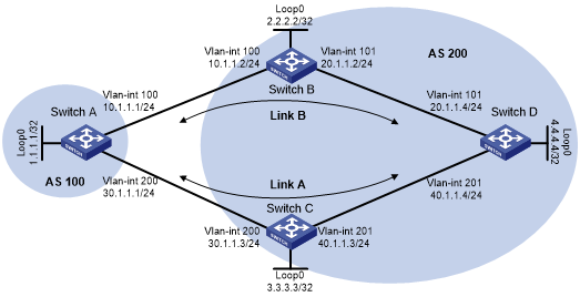
As shown in Figure 78, configure BGP FRR so that when Link B fails, BGP uses Link A to forward traffic.
Figure 78: Network diagram
Configuration procedure
Configure IP addresses for interfaces. (Details not shown.)
Configure OSPF in AS 200 to ensure connectivity among Switch B, Switch C, and Switch D. (Details not shown.)
Configure BGP connections:
# Configure Switch A to establish EBGP sessions to Switch B and Switch C, and advertise network 1.1.1.1/32.
<SwitchA> system-view
[SwitchA] bgp 100
[SwitchA-bgp-default] router-id 1.1.1.1
[SwitchA-bgp-default] peer 10.1.1.2 as-number 200
[SwitchA-bgp-default] peer 30.1.1.3 as-number 200
[SwitchA-bgp-default] address-family ipv4 unicast
[SwitchA-bgp-default-ipv4] peer 10.1.1.2 enable
[SwitchA-bgp-default-ipv4] peer 30.1.1.3 enable
[SwitchA-bgp-default-ipv4] network 1.1.1.1 32
# Configure Switch B to establish an EBGP session to Switch A, and an IBGP session to Switch D.
<SwitchB> system-view
[SwitchB] bgp 200
[SwitchB-bgp-default] router-id 2.2.2.2
[SwitchB-bgp-default] peer 10.1.1.1 as-number 100
[SwitchB-bgp-default] peer 4.4.4.4 as-number 200
[SwitchB-bgp-default] peer 4.4.4.4 connect-interface loopback 0
[SwitchB-bgp-default] address-family ipv4 unicast
[SwitchB-bgp-default-ipv4] peer 10.1.1.1 enable
[SwitchB-bgp-default-ipv4] peer 4.4.4.4 enable
[SwitchB-bgp-default-ipv4] peer 4.4.4.4 next-hop-local
[SwitchB-bgp-default-ipv4] quit
[SwitchB-bgp-default] quit
# Configure Switch C to establish an EBGP session to Switch A, and an IBGP session to Switch D.
<SwitchC> system-view
[SwitchC] bgp 200
[SwitchC-bgp-default] router-id 3.3.3.3
[SwitchC-bgp-default] peer 30.1.1.1 as-number 100
[SwitchC-bgp-default] peer 4.4.4.4 as-number 200
[SwitchC-bgp-default] peer 4.4.4.4 connect-interface loopback 0
[SwitchC-bgp-default] address-family ipv4 unicast
[SwitchC-bgp-default-ipv4] peer 30.1.1.1 enable
[SwitchC-bgp-default-ipv4] peer 4.4.4.4 enable
[SwitchC-bgp-default-ipv4] peer 4.4.4.4 next-hop-local
[SwitchC-bgp-default-ipv4] quit
[SwitchC-bgp-default] quit
# Configure Switch D to establish IBGP sessions to Switch B and Switch C, and advertise network 4.4.4.4/32.
<SwitchD> system-view
[SwitchD] bgp 200
[SwitchD-bgp-default] router-id 4.4.4.4
[SwitchD-bgp-default] peer 2.2.2.2 as-number 200
[SwitchD-bgp-default] peer 2.2.2.2 connect-interface loopback 0
[SwitchD-bgp-default] peer 3.3.3.3 as-number 200
[SwitchD-bgp-default] peer 3.3.3.3 connect-interface loopback 0
[SwitchD-bgp-default] address-family ipv4 unicast
[SwitchD-bgp-default-ipv4] peer 2.2.2.2 enable
[SwitchD-bgp-default-ipv4] peer 3.3.3.3 enable
[SwitchD-bgp-default-ipv4] network 4.4.4.4 32
Configure preferred values so Link B is used to forward traffic between Switch A and Switch D:
# Configure Switch A to set the preferred value to 100 for routes received from Switch B.
[SwitchA-bgp-default-ipv4] peer 10.1.1.2 preferred-value 100
[SwitchA-bgp-default-ipv4] quit
[SwitchA-bgp-default] quit
# Configure Switch D to set the preferred value to 100 for routes received from Switch B.
[SwitchD-bgp-default-ipv4] peer 2.2.2.2 preferred-value 100
[SwitchD-bgp-default-ipv4] quit
[SwitchD-bgp-default] quit
Configure BGP FRR:
# On Switch A, set the source address of BFD echo packets to 11.1.1.1.
[SwitchA] bfd echo-source-ip 11.1.1.1
# Create routing policy frr to set a backup next hop 30.1.1.3 (Switch C) for the route destined for 4.4.4.4/32.
[SwitchA] ip prefix-list abc index 10 permit 4.4.4.4 32
[SwitchA] route-policy frr permit node 10
[SwitchA-route-policy] if-match ip address prefix-list abc
[SwitchA-route-policy] apply fast-reroute backup-nexthop 30.1.1.3
[SwitchA-route-policy] quit
# Use echo-mode BFD to detect the connectivity to Switch D.
[SwitchA] bgp 100
[SwitchA-bgp-default] primary-path-detect bfd echo
# Apply the routing policy to BGP FRR for BGP IPv4 unicast address family.
[SwitchA-bgp-default] address-family ipv4 unicast
[SwitchA-bgp-default-ipv4] fast-reroute route-policy frr
[SwitchA-bgp-default-ipv4] quit
[SwitchA-bgp-default] quit
# On Switch D, set the source address of BFD echo packets to 44.1.1.1.
[SwitchD] bfd echo-source-ip 44.1.1.1
# Create routing policy frr to set a backup next hop 3.3.3.3 (Switch C) for the route destined for 1.1.1.1/32.
[SwitchD] ip prefix-list abc index 10 permit 1.1.1.1 32
[SwitchD] route-policy frr permit node 10
[SwitchD-route-policy] if-match ip address prefix-list abc
[SwitchD-route-policy] apply fast-reroute backup-nexthop 3.3.3.3
[SwitchD-route-policy] quit
# Use echo-mode BFD to detect the connectivity to Switch A.
[SwitchD] bgp 200
[SwitchD-bgp-default] primary-path-detect bfd echo
# Apply the routing policy to BGP FRR for BGP IPv4 unicast address family.
[SwitchD-bgp-default] address-family ipv4 unicast
[SwitchD-bgp-default-ipv4] fast-reroute route-policy frr
[SwitchD-bgp-default-ipv4] quit
[SwitchD-bgp-default] quit
Verifying the configuration
# Display detailed information about the route to 4.4.4.4/32 on Switch A. The output shows the backup next hop for the route.
[SwitchA] display ip routing-table 4.4.4.4 32 verbose

Summary count : 1

Destination: 4.4.4.4/32
   Protocol: BGP             Process ID: 0
  SubProtID: 0x2                    Age: 00h01m52s
       Cost: 0               Preference: 255
      IpPre: N/A             QosLocalID: N/A
        Tag: 0                    State: Active Adv
  OrigTblID: 0x0                OrigVrf: default-vrf
    TableID: 0x2                 OrigAs: 200
      NibID: 0x15000003          LastAs: 200
     AttrID: 0x5               Neighbor: 10.1.1.2
      Flags: 0x10060        OrigNextHop: 10.1.1.2
      Label: NULL           RealNextHop: 10.1.1.2
    BkLabel: NULL             BkNextHop: 30.1.1.3
  Tunnel ID: Invalid          Interface: Vlan-interface 100
BkTunnel ID: Invalid        BkInterface: Vlan-interface 200
   FtnIndex: 0x0           TrafficIndex: N/A
  Connector: N/A
# Display detailed information about the route to 1.1.1.1/32 on Switch D. The output shows the backup next hop for the route.
[SwitchD] display ip routing-table 1.1.1.1 32 verbose

Summary count : 1

Destination: 1.1.1.1/32
   Protocol: BGP             Process ID: 0
  SubProtID: 0x1                    Age: 00h00m36s
       Cost: 0               Preference: 255
      IpPre: N/A             QosLocalID: N/A
        Tag: 0                    State: Active Adv
  OrigTblID: 0x0                OrigVrf: default-vrf
    TableID: 0x2                 OrigAs: 100
      NibID: 0x15000003          LastAs: 100
     AttrID: 0x1               Neighbor: 2.2.2.2
      Flags: 0x10060        OrigNextHop: 2.2.2.2
      Label: NULL           RealNextHop: 20.1.1.2
    BkLabel: NULL             BkNextHop: 40.1.1.3
  Tunnel ID: Invalid          Interface: Vlan-interface 101
BkTunnel ID: Invalid        BkInterface: Vlan-interface 201
   FtnIndex: 0x0           TrafficIndex: N/A
  Connector: N/A