X.25 load sharing application
Network requirements
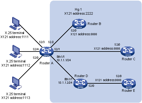
As shown in Figure 146, configure a hunt group on Router A used as an X.25 switch, and enable destination address and source address substitution function, so that the calls from X.25 terminal can be sent to Router B, Router C and Router E through the load sharing function. As an X.25 switch, Router D that connects with Router A and Router E implements the XOT function. As DTEs in hunt group, Router B, Router C and Router E provide the same service for X.25 terminal. Routers B and A use X.25, Routers C and A use FR. Apply Annex G on DLCI to make the two routers communicate with each other.
Figure 146: Network diagram
Configuration procedure
Configure Router A:
# Configure the link layer protocol of interface Serial 2/0 as X.25, and configure it to operate in DCE mode.
<RouterA> system-view
[RouterA] interface serial 2/0
[RouterA-Serial2/0] link-protocol x25 dce
# In the same way, configure the link layer protocol of the interface Serial 2/2, Serial 2/3, and Serial 2/4 as X.25 and configure them to operate in DCE mode.
# Configure Serial 2/1 as an FR DCE.
[RouterA] interface serial 2/1
[RouterA-Serial2/1] link-protocol fr
[RouterA-Serial2/1] fr interface-type dce
# Configure an FR Annex G DLCI.
[RouterA-Serial2/1] fr dlci 100
[RouterA-fr-dlci-Serial2/1-100] annexg dce
[RouterA-fr-dlci-Serial2/1-100] quit
[RouterA-Serial2/1] quit
# Configure interface Ethernet 1/1.
[RouterA] interface ethernet 1/1
[RouterA-Ethernet1/1] ip address 10.1.1.1 255.255.255.0
[RouterA-Ethernet1/1] quit
# Enable X.25 switching.
[RouterA] x25 switching
# Create X.25 hunt group hg1.
[RouterA] x25 hunt-group hg1 round-robin
# Add interfaces Serial 2/2, Serial 2/1, and XOT channel to the hunt group.
[RouterA-hg-hg1] channel interface serial 2/2
[RouterA-hg-hg1] channel interface serial 2/1 dlci 100
[RouterA-hg-hg1] channel xot 10.1.1.2
[RouterA-hg-hg1] quit
# Configure a X.25 switching route forwarded towards the hunt group hg1, and enable destination address and source address substitution, substituting 3333 and 8888 for source and destination addresses of packets destined to hunt group address 2222.
[RouterA] x25 switch svc 2222 sub-dest 8888 sub-source 3333 hunt-group hg1
# Configure X.25 switching route forwarded to the X.25 terminal.
[RouterA] x25 switch svc 1111 interface serial 2/3
[RouterA] x25 switch svc 1112 interface serial 2/4
[RouterA] x25 switch svc 1113 interface serial 2/0
Configure Router B:
# Configure the link layer protocol of interface Serial 2/0 as X.25, and configure it to operate in DTE mode.
<RouterB> system-view
[RouterB] interface serial 2/0
[RouterB-Serial2/0] link-protocol x25 dte
[RouterB-Serial2/0] x25 x121-address 8888
Configure Router C:
# Create an X.25 template.
<RouterC> system-view
[RouterC] x25 template vofr
[RouterC-x25-vofr] x25 x121-address 8888
[RouterC-x25-vofr] quit
# Enable FR on Serial 2/0.
[RouterC] interface serial 2/0
[RouterC-Serial2/0] link-protocol fr
# Configure FR Annex G DLCI.
[RouterC-Serial2/0] fr dlci 100
[RouterC-fr-dlci-Serial2/0-100] annexg dte
# Apply the X.25 template to the DLCI.
[RouterC-fr-dlci-Serial2/0-100] x25-template vofr
Configure Router E:
# Configure the link layer protocol on Serial 2/0 as X.25 and configure it to operate in DTE mode.
<RouterE> system-view
[RouterE] interface serial 2/0
[RouterE-Serial2/0] link-protocol x25 dte
[RouterE-Serial2/0] x25 x121-address 8888
Configure Router D:
# Enable X.25 switching.
<RouterD> system-view
[RouterD] x25 switching
# Configure the link layer protocol of the interface Serial 2/0 as X.25, and configure it to operate in DCE mode.
<RouterD> system-view
[RouterD] interface serial 2/0
[RouterD-Serial2/0] link-protocol x25 dce
[RouterD-Serial2/0] quit
# Assign an IP address for interface Ethernet 1/1.
[RouterD] interface ethernet 1/1
[RouterD-Ethernet1/1] ip address 10.1.1.2 255.255.255.0
[RouterD-Ethernet1/1] quit
# Configure an X.25 switching route to an XOT channel.
[RouterD] x25 switch svc 3333 xot 10.1.1.1
# Configure an X.25 switching route to Router E.
[RouterD] x25 switch svc 8888 interface serial 2/0
Verifying the configuration
# Display the X.25 SVC switching table on Router A.
[RouterA] display x25 switch-table svc static
Number Destination    Substitute-src Substitute-dst CUD      SwitchTo(type/name)
1      2222           3333           8888                    H/hg1
2      1111                                                  I/Serial2/3
3      1112                                                  I/Serial2/4
4      1113                                                  I/Serial2/0
Total of static svc is 4.
The item type of SwitchTo meaning:
  I: interface   H: hunt-group   T: xot
The output shows that the packets destined for 8888 are load-balanced on Router B, Router C, and Router E.