PVC application of X.25 over FR
Network requirements
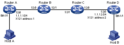
In Figure 145, Router A is connected to Router B, Router C to Router D through X.25, and Router B is connected to Router C through FR.
Configure FR Annex G DLCI 100 on the two routers to interconnect the two X.25 networks, enabling Host A and Host B to communicate with each other.
Figure 145: Network diagram
Configuration procedure
Configure Router A:
# Configure X.25 basic functions.
<RouterA> system-view
[RouterA] interface serial 2/0
[RouterA-Serial2/0] link-protocol x25 dte
[RouterA-Serial2/0] x25 x121-address 1
[RouterA-Serial2/0] x25 vc-range bi-channel 10 20
[RouterA-Serial2/0] x25 pvc 1 ip 1.1.1.2 x121-address 2
[RouterA-Serial2/0] ip address 1.1.1.1 255.255.255.0
Configure Router D:
# Configure X.25 basic functions.
<RouterD> system-view
[RouterD] interface serial 2/0
[RouterD-Serial2/0] link-protocol x25 dte
[RouterD-Serial2/0] x25 x121-address 2
[RouterD-Serial2/0] x25 vc-range bi-channel 10 20
[RouterD-Serial2/0] x25 pvc 1 ip 1.1.1.1 x121-address 1
[RouterD-Serial2/0] ip address 1.1.1.2 255.255.255.0
Configure Router B:
# Enable X.25 switching.
<RouterB> system-view
[RouterB] x25 switching
# Configure the PVC switching route on X.25 interface Serial 2/0.
[RouterB] interface serial 2/0
[RouterB-Serial2/0] link-protocol x25 dce
[RouterB-Serial2/0] x25 vc-range bi-channel 10 20
[RouterB-Serial2/0] x25 switch pvc 1 interface serial 2/1 dlci 100 pvc 1
# Configure X.25 template.
[RouterB] x25 template switch
[RouterB-x25-switch] x25 vc-range bi-channel 10 20
# Configure the PVC switching route for the template.
[RouterB-x25-switch] x25 switch pvc 1 interface serial 2/0 pvc 1
# Configure FR interface Serial 2/1.
[RouterB] interface serial 2/1
[RouterB-Serial2/1] link-protocol fr
[RouterB-Serial2/1] fr interface-type dce
# Configure the FR Annex G DLCI.
[RouterB-Serial2/1] fr dlci 100
[RouterB-fr-dlci-Serial2/1-100] annexg dce
# Apply the X.25 template to the FR Annex G DLCI.
[RouterB-fr-dlci-Serial2/1-100] x25-template switch
Configure Router C:
# Enable X.25 switching.
<RouterC> system-view
[RouterC] x25 switching
# Configure the PVC switching route on the X.25 interface Serial 2/0.
[RouterC] interface serial 2/0
[RouterC-Serial2/0] link-protocol x25 dce
[RouterC-Serial2/0] x25 vc-range bi-channel 10 20
[RouterC-Serial2/0] x25 switch pvc 1 interface serial 2/1 dlci 100 pvc 1
# Configure an X.25 template.
[RouterC] x25 template switch
[RouterC-x25-switch] x25 vc-range bi-channel 10 20
# Configure the PVC switching route for the template.
[RouterC-x25-switch] x25 switch pvc 1 interface serial 2/0 pvc 1
# Configure FR interface Serial 2/1.
[RouterC] interface serial 2/1
[RouterC-Serial2/1] link-protocol fr
# Configure the FR Annex G DLCI.
[RouterC-Serial2/1] fr dlci 100
[RouterC-fr-dlci-Serial2/1-100] annexg dte
# Apply the X.25 template to the FR Annex G DLCI.
[RouterC-fr-dlci-Serial2/1-100] x25-template switch