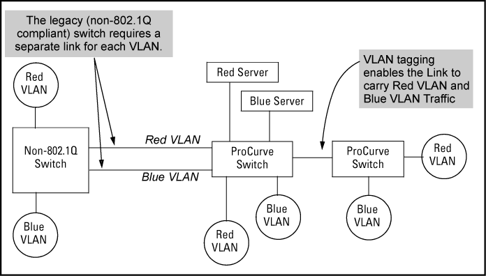
You can introduce 802.1Q-compliant devices into networks that have built untagged VLANs based on earlier VLAN technology. The fundamental rule is that legacy/untagged VLANs require a separate link for each VLAN, while 802.1Q, or tagged VLANs can combine several VLANs in one link. This means that on the 802.1Q-compliant device, separate ports (configured as untagged) must be used to connect separate VLANs to non-802.1Q devices.
|
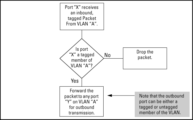
If a port is a tagged member of the same VLAN as an inbound, tagged packet received on that port, then the switch forwards the packet to an outbound port on that VLAN. To enable the forwarding of tagged packets, any VLAN to which the port belongs as a tagged member must have the same VID as that carried by the inbound, tagged packets generated on that VLAN. |
|
|
|
![[CAUTION: ]](images/caution.gif) |
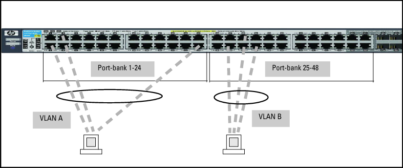
CAUTION: Rate limiting may behave unpredictably on a VLAN if the VLAN spans multiple modules or port-banks. This also applies if a port on a different module or port-bank is added to an existing VLAN. HP does not recommend configuring rate limiting on VLANs that include ports spanning modules or port-banks. |
|
|
In the following example, ports 2, 3, and 24 form one VLAN, with ports 1 through 24 in the same port-bank. Ports 28, 29, and 32 form a second VLAN. These ports are also in the same port-bank, which includes ports 25 through 48. Rate limiting will operate as expected for these VLANs.
Switches use a forwarding database to maintain awareness of which external devices are located on which VLANs. Some switches, such as the switches covered in this guide, have a multiple forwarding database, which means the switch allows multiple database entries of the same MAC address, with each entry showing the (different) source VLAN and source port. Other switch models have a single forwarding database, which allows only one database entry of a unique MAC address, along with the source VLAN and source port on which it is found. All VLANs on a switch use the same MAC address. Thus, connecting a multiple forwarding database switch to a single forwarding database switch where multiple VLANs exist imposes some cabling and port VLAN assignment restrictions. The following table illustrates the functional difference between the two database types.
Forwarding database content
| Multiple forwarding database | Single forwarding database | ||||
|---|---|---|---|---|---|
| MAC address | Destination VLAN ID | Destination port | MAC address | Destination VLAN ID | Destination port |
| 0004ea-84d9f4 | 1 | A5 | 0004ea-84d9f4 | 100 | A9 |
| 0004ea-84d9f4 | 22 | A12 | 0060b0-880af9 | 105 | A10 |
| 0004ea-84d9f4 | 44 | A20 | 0060b0-880a81 | 107 | A17 |
| 0060b0-880a81 | 33 | A20 | |||
|
This database allows multiple destinations for the same MAC address. If the switch detects a new destination for an existing MAC entry, it just adds a new instance of that MAC to the table. |
This database allows only one destination for a MAC address. If the switch detects a new destination for an existing MAC entry, it replaces the existing MAC instance with a new instance showing the new destination. |
||||
Forwarding database structure for managed HP switches
| Multiple forwarding databases[a] | Single forwarding database[a] |
|---|---|
| Series 8200zl switches | Switch 1600M/2400M/2424M |
| Switch 6600 | Switch 4000M/8000M |
| Series 6400cl switches | Series 2500 switches |
| Switch 6200yl | Switch 2000 |
| Switch 6108 | Switch 800T |
| Series 5400zl switches | |
| Series 5300xl switches | |
| Series 4200vl switches | |
| Series 4100gl switches | |
| Series 3800 switches | |
| Series 3500 switches | |
| Series 3500yl switches | |
| Series 3400cl switches | |
| Switch 2810 | |
| Series 2800 switches | |
| Series 2600/2600-PWR switches | |
| Series 2510 switches | |
|
[a] To determine whether other vendors' devices use single-forwarding or multiple-forwarding database architectures, see the documentation provided for those devices. |
|
When a packet arrives with a destination MAC address that matches a MAC address in the switch's forwarding table, the switch tries to send the packet to the port listed for that MAC address. But if the destination port is in a different VLAN than the VLAN on which the packet was received, the switch drops the packet. This is not a problem for a switch with a multiple forwarding database, because the switch allows multiple instances of a given MAC address; one for each valid destination. However, a switch with a single forwarding database allows only one instance of a given MAC address.
If (1) two types of switches connect through multiple ports or trunks belonging to different VLANs, and (2) routing is enabled on the switch having the multiple forwarding database then, on the switch having the single forwarding database, the port and VLAN record it maintained for the connected multiple-forwarding-database switch on the switch having the single forwarding database, maintains for the connected multiple-forwarding-database switch can frequently change. This causes poor performance and the appearance of an intermittent or broken connection.
-
The switch requires VLAN tagging on a given port if more than one VLAN of the same type uses the port. When a port belongs to two or more VLANs of the same type, they remain as separate broadcast domains and cannot receive traffic from each other without routing.
-
The switch requires VLAN tagging on a given port if the port will be receiving inbound, tagged VLAN traffic that should be forwarded. Even if the port belongs to only one VLAN, it forwards inbound tagged traffic only if it is a tagged member of that VLAN.
-
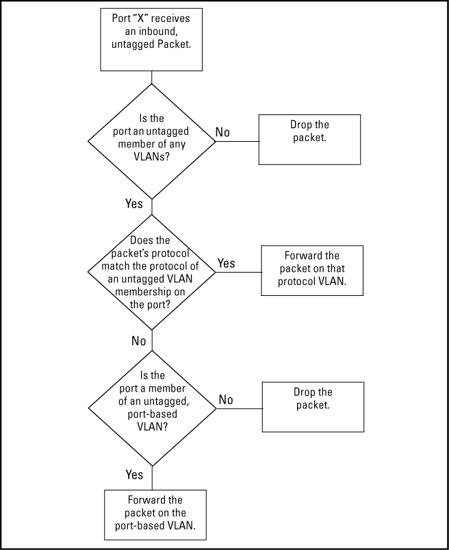
If the only authorized, inbound VLAN traffic on a port arrives untagged, then the port must be an untagged member of that VLAN. This is the case where the port is connected to a non 802.1Q-compliant device or is assigned to only one VLAN.
Tagged and untagged VLAN port assignments
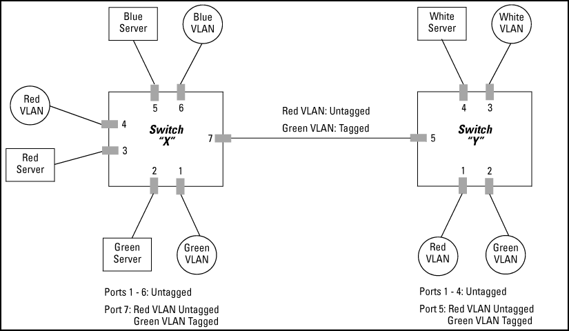
If port 7 on an 802.1Q-compliant switch is assigned to only the Red VLAN, the assignment can remain "untagged" because the port will forward traffic only for the Red VLAN. However, if both the Red and Green VLANs are assigned to port 7, then at least one of those VLAN assignments must be "tagged" so that Red VLAN traffic can be distinguished from Green VLAN traffic.
-
VLANs assigned to ports X1 - X6 can be untagged because there is only one VLAN assignment per port. Red VLAN traffic will go out only the Red ports, Green VLAN traffic will go out only the Green ports, and so on. Devices connected to these ports do not have to be 802.1Q-compliant.
-
However, because both the Red VLAN and the Green VLAN are assigned to port X7, at least one of the VLANs must be tagged for this port.
-
VLANs assigned to ports Y1 - Y4 can be untagged because there is only one VLAN assignment per port. Devices connected to these ports do not have to be 802.1Q-compliant.
-
Because both the Red VLAN and the Green VLAN are assigned to port Y5, at least one of the VLANs must be tagged for this port.
-
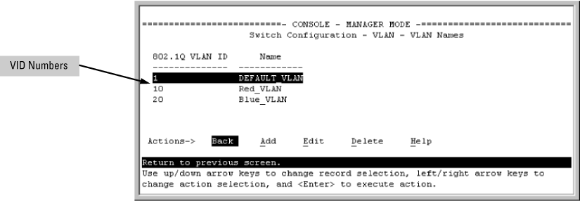
The ports on the link between the two switches must be configured the same. As shown in VLAN ID numbers assigned in the VLAN names screen, the Red VLAN must be untagged on port X7 and Y5 and the Green VLAN must be tagged on port X7 and Y5, or vice-versa.
-
Since the purpose of VLAN tagging is to allow multiple VLANs on the same port, any port that has only one VLAN assigned to it can be configured as "Untagged" (the default) if the authorized inbound traffic for that port arrives untagged.
-
Any port with two or more VLANs of the same type can have one such VLAN assigned as "Untagged." All other VLANs of the same type must be configured as "Tagged," that is:
Port-Based VLANs Protocol VLANs A port can be a member of one untagged, port-based VLAN. All other port-based VLAN assignments for that port must be tagged. A port can be an untagged member of one protocol-based VLAN of each protocol type. When assigning a port to multiple, protocol-based VLANs sharing the same type, the port can be an untagged member of only one such VLAN. A port can be a tagged member of any port-based VLAN. A port can be a tagged member of any protocol-based VLAN.
![[NOTE: ]](images/note.gif)
NOTE: A given VLAN must have the same VID on all 802.1Q-compliant devices in which the VLAN occurs. Also, the ports connecting two 802.1Q devices should have identical VLAN configurations.
-
If all end nodes on a port comply with the 802.1Q standard and are configured to use the correct VID, you can configure all VLAN assignments on a port as "Tagged" if doing so either makes it easier to manage your VLAN assignments, or if the authorized, inbound traffic for all VLANs on the port will be tagged.
Networked 802.1Q-compliant devices with multiple VLANs on some ports
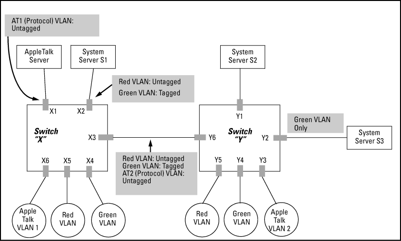
Network, switches X and Y and servers S1, S2, and the AppleTalk server are 802.1Q-compliant. (Server S3 could also be 802.1Q-compliant. This network includes both protocol-based (AppleTalk) VLANs and port-based VLANs.
-
The VLANs assigned to ports X4 - X6 and Y2 - Y5 can all be untagged because there is only one VLAN assigned per port.
-
Port X1 has two AppleTalk VLANs assigned, which means that one VLAN assigned to this port can be untagged and the other must be tagged.
-
Ports X2 and Y1 have two port-based VLANs assigned, so one can be untagged and the other must be tagged on both ports.
-
Ports X3 and Y6 have two port-based VLANs and one protocol-based VLAN assigned. Thus, one port-based VLAN assigned to this port can be untagged and the other must be tagged. Also, since these two ports share the same link, their VLAN configurations must match.
| Switch X | Switch Y | ||||||||
|---|---|---|---|---|---|---|---|---|---|
| Port | AT-1 VLAN | AT-2 VLAN | Red VLAN | Green VLAN | Port | AT-1 VLAN | AT-2 VLAN | Red VLAN | Green VLAN |
| X1 | Untagged | Tagged | No[*] | No[*] | Y1 | No[*] | No[*] | Untagged | Tagged |
| X2 | No[*] | No[*] | Untagged | Tagged | Y2 | No[*] | No[*] | No[*] | Untagged |
| X3 | No[*] | Untagged | Untagged | Tagged | Y3 | No[*] | Untagged | No[*] | No[*] |
| X4 | No[*] | No[*] | No[*] | Untagged | Y4 | No[*] | No[*] | No[*] | Untagged |
| X5 | No[*] | No[*] | Untagged | No[*] | Y5 | No[*] | No[*] | Untagged | No[*] |
| X6 | Untagged | No[*] | No[*] | No[*] | Y6 | No | Untagged | Untagged | Tagged |
|
[*] No means the port is not a member of that VLAN. For example, port X3 is not a member of the Red VLAN and does not carry Red VLAN traffic. Also, if GVRP were enabled (port-based only), Auto would appear instead of No. |
|||||||||
In the factory default configuration, VLAN support is enabled and all ports on the switch belong to the port-based, default VLAN (named DEFAULT_VLAN). This places all ports in the switch into one physical broadcast domain. In the factory-default state, the default VLAN is also the Primary VLAN.
-
You can partition the switch into multiple virtual broadcast domains by configuring one or more additional VLANs and moving ports from the default VLAN to the new VLANs.
-
The switch supports up to 2048 static and dynamic VLANs, with VIDs numbered up to 4094. You can change the name of the default VLAN, but not its VID, which is always 1.
-
You can remove all ports from the default VLAN by placing them in another port-based VLAN, but this VLAN remains and cannot be deleted from the switch.
As certain features and management functions run on only one VLAN in the switch, and because DHCP and Bootp can run per-VLAN, there is a need for a dedicated VLAN to manage these features and ensure that multiple instances of DHCP or Bootp on different VLANs do not result in conflicting configuration values for the switch.
The Primary VLAN is the VLAN the switch uses to run and manage these features and data. In the factory-default configuration, the switch designates the default VLAN (DEFAULT_VLAN; VID=1) as the Primary VLAN. However you can designate another static, port-based VLAN as primary.
To summarize, designating a non-default VLAN as primary means that:
-
The switch reads DHCP responses on the Primary VLAN instead of on the default VLAN. This includes such DHCP-resolved parameters as the TimeP server address, Default TTL, and IP addressing—including the Gateway IP address—when the switch configuration specifies DHCP as the source for these values.
-
The default VLAN continues to operate as a standard VLAN you cannot delete it or change its VID.
-
Any ports not specifically assigned to another VLAN will remain assigned to the Default VLAN, even if it is the Primary VLAN.
Candidates for Primary VLAN include any static, port-based VLAN currently configured on the switch.
Protocol-Based VLANs and dynamic (GVRP-learned) VLANs that have not been converted to a static VLAN cannot be the Primary VLAN. To display the current Primary VLAN, use the CLI show vlan command.
Configuring a secure Management VLAN creates an isolated network for managing the HP switches that support this feature. Access to a secure Management VLAN and the switch's management functions (Menu and CLI), is available only through ports configured as members.
-
Multiple ports on the switch can belong to the Management VLAN. This allows connections for multiple management stations to the Management VLAN, while allowing Management VLAN links between switches configured for the same Management VLAN.
-
Only traffic from the Management VLAN can manage the switch, which means that only the workstations and PCs connected to ports belonging to the Management VLAN can manage and reconfigure the switch.
Potential security breaches in a network
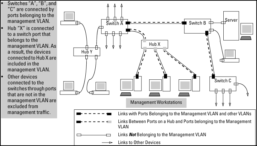
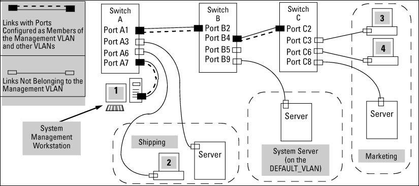
This illustrates use of the Management VLAN feature to support management access by a group of management workstations.
Management VLAN control in a LAN
Workstation 1 has management access to all three switches through the Management VLAN, while the PCs do not. This is because configuring a switch to recognize a Management VLAN automatically excludes attempts to send management traffic from any other VLAN.
VLAN membership in Management VLAN control in a LAN
| Switch | A1 | A3 | A6 | A7 | B2 | B4 | B5 | B9 | C2 | C3 | C6 | C8 |
|---|---|---|---|---|---|---|---|---|---|---|---|---|
| Management VLAN (VID = 7) | Y | N | N | Y | Y | Y | N | N | Y | N | N | N |
| Marketing VLAN (VID = 12) | N | N | N | N | N | N | N | N | N | Y | Y | Y |
| Shipping Dept. VLAN (VID = 20) | N | Y | Y | N | N | N | N | N | N | N | N | N |
| DEFAULT-VLAN (VID = 1) | Y | Y | Y | Y | Y | Y | Y | Y | Y | Y | Y | Y |
-
The Management VLAN feature applies to both IPv4 and IPv6 traffic.
-
Routing between the Management VLAN and other VLANs is not allowed.
-
If there are more than 25 VLANs configured on the switch, reboot the switch after configuring the Management VLAN.
-
If you implement a Management VLAN in a switch mesh environment, all meshed ports on the switch will be members of the Management VLAN.
-
Only one Management VLAN can be active in the switch. If one Management VLAN VID is saved in the
startup-configfile and you configure a different VID in therunning-configfile, the switch uses the running-config version until you either use thewrite-memorycommand or reboot the switch. -
During a Telnet session to the switch, if you configure the Management VLAN to a VID that excludes the port through which you are connected to the switch, you will continue to have access only until you terminate the session by logging out or rebooting the switch.
![[NOTE: ]](images/note.gif)
NOTE: The Management VLAN feature does not control management access through a direct connection to the switch's serial port.
-
During a WebAgent session, if you configure the Management VLAN to a VID that excludes the port through which you are connected to the switch, you will continue to have access only until you close the browser session or reboot the switch.
-
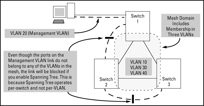
Enabling Spanning Tree between a pair of switches where there are multiple links using separate VLANs, including the Management VLAN, will force the blocking of one or more links. This may include the link carrying the Management VLAN, which will cause loss of management access to some devices. This can also occur where meshing is configured and the Management VLAN is configured on a separate link.
-
Monitoring Shared Resources: The Management VLAN feature shares internal switch resources with several other features. The switch provides ample resources for all features. However, if the internal resources become fully subscribed, the Management VLAN feature cannot be configured until the necessary resources are released from other uses. For information on determining the current resource availability and usage, see the Management and Configuration Guide for your switch.
Configuring voice VLANs separates voice traffic from data traffic and shields your voice traffic from broadcast storms.
-
You must statically configure voice VLANs. GVRP and dynamic VLANs do not support voice VLAN operation.
-
Configure all ports in a voice VLAN as tagged members of the VLAN. This ensures retention of the QoS (Quality of Service) priority included in voice VLAN traffic moving through your network.
-
If a telephone connected to a voice VLAN includes a data port used for connecting other networked devices (such as PCs) to the network, then you must configure the port as a tagged member of the voice VLAN and a tagged or untagged member of the data VLAN you want the other networked device to use.
-
Voice VLAN: Configure one or more voice VLANs on the switch. Some reasons for having multiple voice VLANs include:
Where multiple voice VLANs exist on the switch, you can use routing to communicate between telephones on different voice VLANs.
-
Tagged/Untagged VLAN Membership: If the appliances using a voice VLAN transmit tagged VLAN packets, then configure the member ports as tagged members of the VLAN. Otherwise, configure the ports as untagged members.
Depending on the spanning tree option configured on the switch, the spanning tree feature may operate as:
For single-instance operation, this means that if redundant physical links exist between the switch and another 802.1Q device, all but one link will be blocked, even if the redundant links are in separate VLANs. In this case you can use port trunking to prevent Spanning Tree from unnecessarily blocking ports (and to improve overall network performance). For multiple-instance operation, physically redundant links belonging to different VLANs can remain open.
Note that Spanning Tree operates differently in different devices. For example, in the (obsolete, non-802.1Q) HP Switch 2000 and the HP Switch 800T, Spanning Tree operates on a per-VLAN basis, allowing redundant physical links as long as they are in separate VLANs.
There is a one-to-one relationship between a VLAN and an IP network interface. Since the VLAN is defined by a group of ports, the state (up/down) of those ports determines the state of the IP network interface associated with that VLAN. When a port-based VLAN or an IPv4 or IPv6 protocol-based VLAN comes up because one or more of its ports is up, the IP interface for that VLAN is also activated. Likewise, when a VLAN is deactivated because all of its ports are down, the corresponding IP interface is also deactivated.
The switches have one unique MAC address for all of their VLAN interfaces. You can send an 802.2 test packet to this MAC address to verify connectivity to the switch. Likewise, you can assign an IP address to the VLAN interface, and when you Ping that address, ARP will resolve the IP address to this single MAC address.
In a topology where a switch has multiple VLANs and must be connected to a device having a single forwarding database, such as the Switch 4000M, some cabling restrictions apply.
When assigning a port trunk to a VLAN, all ports in the trunk are automatically assigned to the same VLAN. Do not split trunk members across multiple VLANs. A port trunk is tagged, untagged, or excluded from a VLAN in the same way as individual, untrunked ports.
If you designate a port on the switch for network monitoring, this port will appear in the PortVLAN Assignment screen and can be configured as a member of any VLAN. For information on how broadcast, multicast, and unicast packets are tagged inside and outside of the VLAN to which the monitor port is assigned, see the Management and Configuration Guide for your switch.
-
A port must be a member of at least one VLAN. In the factory default configuration, all ports are assigned to the default VLAN (DEFAULT_VLAN; VID=1).
-
A port can be a member of one untagged, port-based VLAN. All other port-based VLAN assignments for that port must be tagged. The "Untagged" designation enables VLAN operation with non 802.1Q-compliant devices.
-
A port can be an untagged member of one protocol-based VLAN of each protocol type. When assigning a port to multiple, protocol-based VLANs sharing of the same type, note that the port can be an untagged member of only one such VLAN.
-
With routing enabled on the switch, the switch can route traffic between:
Other, routable, protocol-based VLANs must use an external router to move traffic between VLANs. With routing disabled, all routing between VLANs must be through an external router.
-
Prior to deleting a static VLAN, you must first re-assign all ports in the VLAN to another VLAN. You can use the
no vlancommand to delete a static VLAN.vid -
Protocol-based VLANs, port-based VLANs and LLDP radio port VLANs cannot run concurrently with RPVST+.
HP switches provide for maintaining Layer 3 VLAN configurations when migrating distribution routers in networks not centrally managed, by configuring the MAC address of the previous router on the VLAN interfaces of the HP routing switch.
HP switches use one unique MAC address for all VLAN interfaces. If you assign an IP address to a VLAN interface, ARP resolves the IP address to the MAC address of the routing switch for all incoming packets.
The Layer 3 VLAN MAC Configuration feature allows you to reconfigure the MAC address used for VLAN interfaces, using the CLI. Packets addressed to the reconfigured Layer 3 MAC address, such as ARP and IP data packets, are received and processed by the HP routing switch.
Packets transmitted from the routing switch (packets originating from the router and forwarded packets) use the original HP Switch MAC address as the source MAC address in Ethernet headers.
ARP reply packets use the reconfigured MAC address in both the:
-
ARP Sender MAC address field
-
Source MAC address field in the Ethernet frame header
When reconfiguring the MAC address, you may specify a keepalivetimeout to transmit heartbeat packets that advertise the new MAC address
By configuring the MAC address of the previously installed router as the MAC address of each VLAN interface on an HP Switch, you can swap the physical port of a router to the HP Switch after the switch has been properly configured in the network.
These are received and processed on the routing switch according to the MAC address of the previously installed router that is configured for each VLAN interface.
This uses the MAC address of the HP Switch as the source MAC address in packet headers. The MAC address configured on VLAN interfaces is not used on outbound VLAN traffic.
When the routing switch receives an ARP request for the IP address configured on a VLAN interface, the ARP reply uses the reconfigured MAC address in both the:
-
ARP Sender MAC address field
-
Source MAC address field in the Ethernet frame header
When proxy ARP is enabled on a VLAN interface, the "gracious" ARP reply sent for an ARP request received from VLAN devices located outside the directly connected IP subnets also contains the reconfigured MAC address in both the:
-
ARP Sender MAC address field
-
Source MAC address field in the Ethernet frame header
|
|
|
![[NOTE: ]](images/note.gif) |
NOTE: The Virtual Router Redundancy Protocol (VRRP) is not supported on VLAN interfaces on which the MAC address for incoming traffic has been reconfigured. |
|
|
To hosts in the network, VLAN traffic continues to be routed (using the reconfigured MAC address as destination address), but outbound VLAN traffic appears to be sent from another router attached to the same subnet (using the HP Switch MAC address as source address) attached to the same subnet . Although it appears as an asymmetric path to network hosts, the MAC address configuration feature enables Layer 3 VLAN migration. (A successful VLAN migration is achieved because the hosts do not verify that the source MAC address and the destination MAC address are the same when communicating with the routing switch.)
On the VLAN interfaces of a routing switch, the user-defined MAC address only applies to inbound traffic. As a result, any connected switches need to learn the new address that is included in the Ethernet frames of outbound VLAN traffic transmitted from the routing switch.
If a connected switch does not have the newly configured MAC address of the routing switch as a destination in its MAC address table, it floods packets to all of its ports until a return stream allows the switch to learn the correct destination address. As a result, the performance of the switch is degraded as it tries to send Ethernet packets to an unknown destination address.
To allow connected switches to learn the user-configured MAC address of a VLAN interface, the HP routing switch can send periodic heartbeat-like Ethernet packets. The Ethernet packets contain the configured MAC address as the source address in the packet header. IP multicast packets or Ethernet service frames are preferred because they do not interrupt the normal operation of client devices connected on the segment.
Because the aging time of destination addresses in MAC address tables varies on network devices, you must also configure a time interval to use for sending heartbeat packets.
Heartbeat packets are sent at periodic intervals with a specific HP Switch unicast MAC address in the destination field. This MAC address is assigned to the HP Switch and is not used by other non-HP routers. Because the heartbeat packet contains a unicast MAC address, it does not interrupt host operation. Even if you have multiple 1-65 Static Virtual LANs (VLANs) Introducing tagged VLAN technology into networks running untagged VLANs HP switches connected to the network, there is no impact on network performance because each switch sends heartbeat packets with its configured MAC address as the destination address.
The format of a heartbeat packet is an extended Ethernet OUI frame with an extended OUI Ethertype (88B7) and a new protocol identifier in the 5-octet protocol identifier field.
-
The
ip-recv-mac-addresscommand allows you to configure only one MAC address for a specified VLAN. If you re-enter the command to configure another MAC address, the previously configured MAC address is overwritten. -
Enter the
noform of the command to remove a configured MAC address and restore the default MAC address of the HP switch. -
When you configure a VLAN MAC address, you may also specify a heartbeat interval. The
intervalparameter is optional.seconds -
Immediately after you configure a VLAN MAC address or remove a configured MAC address, a gratuitous ARP message is broadcast on the connected segment to announce the change of the IP-to-MAC address binding to all connected IP-based equipment.
-
A configured VLAN MAC address supports proxy ARP and gracious ARP.
-
A new MIB variable,
ifRcvAddressTable, is introduced to support VLAN MAC configuration. -
You cannot configure a VLAN MAC address using the WebAgent or menu interface. You must use the CLI.
-
VRRP is not supported on a VLAN interface with a user-configured MAC address.
