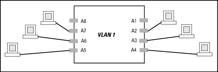
A group of networked ports assigned to a VLAN form a broadcast domain configured on the switch. On a given switch, packets are bridged between source and destination ports that belong to the same VLAN. Thus, all ports passing traffic for a particular subnet address should be configured to the same VLAN. Cross-domain broadcast traffic in the switch is eliminated and bandwidth is saved by not allowing packets to flood out all ports.
Comparative operation of port based and protocol based VLANs
You can configure different VLAN types in any combination. The default VLAN will always be present.
-
A VLAN is composed of multiple ports operating as members of the same subnet or broadcast domain.
-
Traffic moving between ports in the same VLAN is bridged (or switched).
-
A static VLAN is an 802.1Q-compliant VLAN, configured with one or more ports that remain members regardless of traffic usage.
-
A dynamic VLAN is an 802.1Q-compliant VLAN membership that the switch temporarily creates on a port to provide a link to another port either in the same VLAN on another device.
This type of static VLAN creates a specific layer-2 broadcast domain comprised of member ports that bridge IPv4 traffic among themselves. Port-Based VLAN traffic is routable on the switches covered in this guide.
This type of static VLAN creates a layer-3 broadcast domain for traffic of a particular protocol, and is composed of member ports that bridge traffic of the specified protocol type among themselves. Some protocol types are routable on the switches covered in this guide; see Comparative operation of port based and protocol based VLANs.
The switch uses these static, port-based VLAN types to separate switch management traffic from other network traffic. While these VLANs are not limited to management traffic, they provide improved security and availability.
|
|
|
![[NOTE: ]](images/note.gif) |
NOTE: In a multiple-VLAN environment that includes older switch models there may be problems related to the same MAC address appearing on different ports and VLANs on the same switch. In such cases the solution is to impose cabling and VLAN restrictions. |
|
|
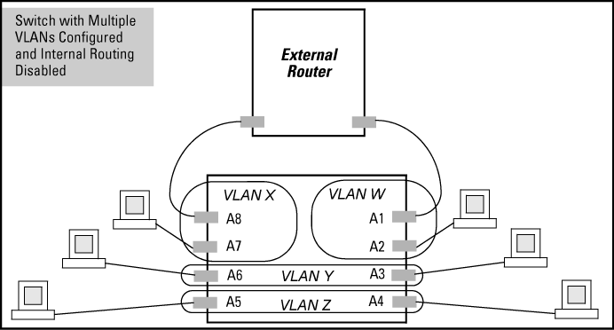
In A switch with multiple VLANs configured and internal routing disabled, routing within the switch is disabled (the default). This means that communication between any routable VLANs on the switch must go through the external router. In this case, VLANs W and X can exchange traffic through the external router, but traffic in VLANs Y and Z is restricted to the respective VLANs.
Note that VLAN 1(the default) is present but not shown. The default VLAN cannot be deleted from the switch, but ports assigned to other VLANs can be removed from the default VLAN. If internal (IP) routing is enabled on the switch, then the external router is not needed for traffic to move between port-based VLANs.
A switch with multiple VLANs configured and internal routing disabled illustrates a protocol VLAN environment also. In this case, VLANs W and X represent routable protocol VLANs. VLANs Y and Z can be any protocol VLAN.
As noted for the discussion of multiple port-based VLANs, VLAN 1 is not shown. Enabling internal (IP) routing on the switch allows IP traffic to move between VLANs on the switch, but routable, non-IP traffic always requires an external router.
Options for routing between VLAN types in the switch
| Port-Based | IPX | IPv4 | IPv6 | ARP | AppleTalk | SNA[2] | NETbeui[2] | ||
|---|---|---|---|---|---|---|---|---|---|
| Port-Based | Yes | — | Yes | — | — | — | — | — | |
| Protocol | IPX | — | Yes[1] | — | — | — | — | — | — |
| IPX4 | Yes | — | Yes | — | — | — | — | — | |
| IPV6 | — | — | — | Yes[1] | — | — | — | — | |
| ARP | — | — | — | — | Yes[1] | — | — | — | |
| AppleTalk | — | — | — | — | — | Yes[1] | — | — | |
| SNA | — | — | — | — | — | — | — | — | |
| NETbeui | — | — | — | — | — | — | — | — | |
|
[2] Not a routable protocol type. End stations intended to receive traffic in these protocols must be attached to the same physical network. [1] Requires an external router to route between VLANs. |
|||||||||
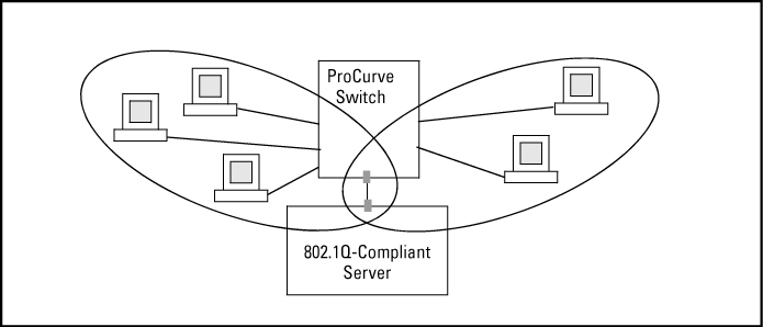
A port can be a member of more than one VLAN of the same type if the device to which the port connects complies with the 802.1Q VLAN standard.
For example, a port connected to a central server using a network interface card (NIC) that complies with the 802.1Q standard can be a member of multiple VLANs, allowing members of multiple VLANs to use the server.
-
Although these VLANs cannot communicate with each other through the server, they can all access the server over the same connection from the switch.
-
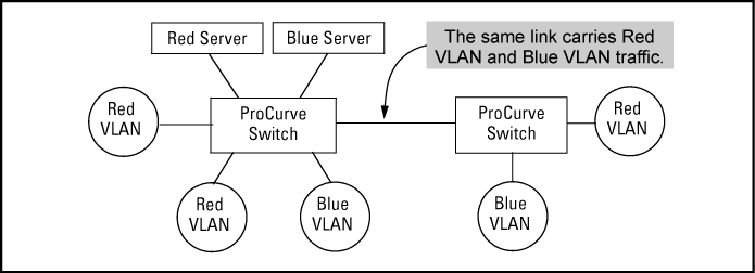
Where VLANs overlap in this way, VLAN "tags" are used in the individual packets to distinguish between traffic from different VLANs.
-
A VLAN tag includes the particular VLAN I.D. (VID) of the VLAN on which the packet was generated.
Similarly, using 802.1Q-compliant switches, you can connect multiple VLANs through a single switch-to-switch link.


