Planning the cabling scheme
Use twisted pair cables, SFP+ cables, or SFP+ transceiver modules and fibers to connect the IRF member switches. If the IRF member switches are far away from one another, choose the SFP+ transceiver modules with optical fibers. If the IRF member switches are all in one equipment room, choose twisted pair cables or SFP+ cables.
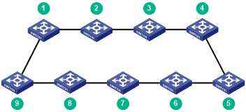
As a best practice, use ring topology to connect the switches. The following describes cabling schemes in ring topology.
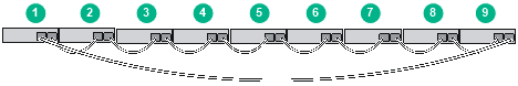
Connecting the IRF member switches in one rack
Use SFP+ cables to connect the IRF member switches (9 switches in this example) in a rack as shown in Figure 30. The switches in the ring topology (see Figure 31) are in the same order as connected in the rack.
Figure 30: Connecting the switches in one rack
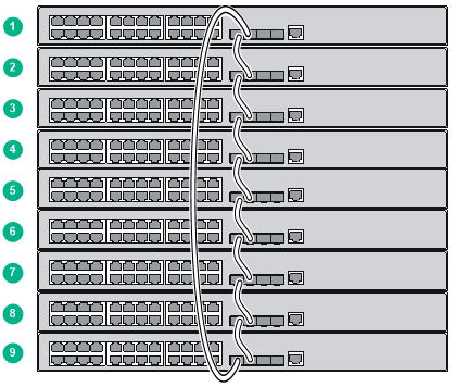
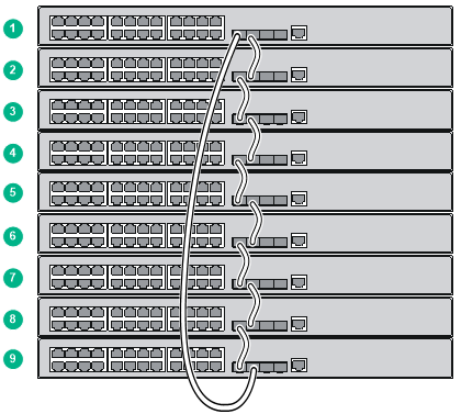
Figure 31: IRF fabric topology
Connecting the IRF member switches in a ToR solution
You can install IRF member switches in different racks side by side to deploy a top of rack (ToR) solution.
Figure 32 shows an example for connecting 9 top of rack IRF member switches by using SFP+ transceiver modules and optical fibers. The topology is the same as Figure 31.
Figure 32: ToR cabling