BGP load balancing configuration example
Network requirements
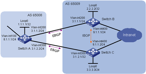
As shown in Figure 62, run EBGP between Switch A and Switch B and between Switch A and Switch C. Run IBGP between Switch B and Switch C. Configure load balancing over the two EBGP links on Switch A.
Figure 62: Network diagram
Configuration considerations
On Switch A, establish EBGP connections with Switch B and Switch C. Configure BGP to advertise network 8.1.1.0/24 to Switch B and Switch C, so that Switch B and Switch C can access the internal network connected to Switch A.
On Switch B, establish an EBGP connection with Switch A and an IBGP connection with Switch C. Configure BGP to advertise network 9.1.1.0/24 to Switch A, so that Switch A can access the intranet through Switch B. Configure a static route to interface loopback 0 on Switch C (or use a routing protocol like OSPF) to establish the IBGP connection.
On Switch C, establish an EBGP connection with Switch A and an IBGP connection with Switch B. Configure BGP to advertise network 9.1.1.0/24 to Switch A, so that Switch A can access the intranet through Switch C. Configure a static route to interface loopback 0 on Switch B (or use another protocol like OSPF) to establish the IBGP connection.
Configure load balancing on Switch A.
Configuration procedure
Configure IP addresses for interfaces. (Details not shown.)
Configure BGP connections:
# Configure Switch A.
<SwitchA> system-view
[SwitchA] bgp 65008
[SwitchA-bgp] router-id 1.1.1.1
[SwitchA-bgp] peer 3.1.1.1 as-number 65009
[SwitchA-bgp] peer 3.1.2.1 as-number 65009
[SwitchA-bgp] address-family ipv4 unicast
[SwitchA-bgp-ipv4] peer 3.1.1.1 enable
[SwitchA-bgp-ipv4] peer 3.1.2.1 enable
[SwitchA-bgp-ipv4] network 8.1.1.1 24
[SwitchA-bgp-ipv4] quit
[SwitchA-bgp] quit
# Configure Switch B.
<SwitchB> system-view
[SwitchB] bgp 65009
[SwitchB-bgp] router-id 2.2.2.2
[SwitchB-bgp] peer 3.1.1.2 as-number 65008
[SwitchB-bgp] peer 3.3.3.3 as-number 65009
[SwitchB-bgp] peer 3.3.3.3 connect-interface loopback 0
[SwitchB-bgp] address-family ipv4 unicast
[SwitchB-bgp-ipv4] peer 3.1.1.2 enable
[SwitchB-bgp-ipv4] peer 3.3.3.3 enable
[SwitchB-bgp-ipv4] network 9.1.1.0 24
[SwitchB-bgp-ipv4] quit
[SwitchB-bgp] quit
[SwitchB] ip route-static 3.3.3.3 32 9.1.1.2
# Configure Switch C.
<SwitchC> system-view
[SwitchC] bgp 65009
[SwitchC-bgp] router-id 3.3.3.3
[SwitchC-bgp] peer 3.1.2.2 as-number 65008
[SwitchC-bgp] peer 2.2.2.2 as-number 65009
[SwitchC-bgp] peer 2.2.2.2 connect-interface loopback 0
[SwitchC-bgp] address-family ipv4 unicast
[SwitchC-bgp-ipv4] peer 3.1.2.2 enable
[SwitchC-bgp-ipv4] peer 2.2.2.2 enable
[SwitchC-bgp-ipv4] network 9.1.1.0 24
[SwitchC-bgp-ipv4] quit
[SwitchC-bgp] quit
[SwitchC] ip route-static 2.2.2.2 32 9.1.1.1
# Display the BGP routing table on Switch A.
[SwitchA] display bgp routing-table ipv4

 Total number of routes: 3

 BGP local router ID is 1.1.1.1
 Status codes: * - valid, > - best, d - damped, h - history,
               s - suppressed, S - Stale, i - internal, e - external
               Origin: i - IGP, e - EGP, ? - incomplete

     Network            NextHop         MED        LocPrf     PrefVal Path/Ogn

* >  8.1.1.0/24         8.1.1.1         0                     0       i
* >e 9.1.1.0/24         3.1.1.1         0                     0       65009i
*  e                    3.1.2.1         0                     0       65009i
The output shows two valid routes to destination 9.1.1.0/24. The route with next hop 3.1.1.1 is marked with a greater-than sign (>), indicating it is the best route (because the ID of Switch B is smaller). The route with next hop 3.1.2.1 is marked with an asterisk (*), indicating it is a valid route, but not the best.
By using the display ip routing-table command, you can find only one route to 9.1.1.0/24 with next hop 3.1.1.1 and outbound interface VLAN-interface 200.
Configure loading balancing:
Because Switch A has two routes to reach AS 65009, configuring load balancing over the two BGP routes on Switch A can improve link usage.
# Configure Switch A.
[SwitchA] bgp 65008
[SwitchA-bgp] address-family ipv4 unicast
[SwitchA-bgp-ipv4] balance 2
[SwitchA-bgp-ipv4] quit
[SwitchA-bgp] quit
Verifying the configuration
# Display the BGP routing table on Switch A.
[SwitchA] display bgp routing-table ipv4

 Total number of routes: 3

 BGP local router ID is 1.1.1.1
 Status codes: * - valid, > - best, d - damped, h - history,
               s - suppressed, S - Stale, i - internal, e - external
               Origin: i - IGP, e - EGP, ? - incomplete

     Network            NextHop         MED        LocPrf     PrefVal Path/Ogn

* >  8.1.1.0/24         8.1.1.1         0                     0       i
* >e 9.1.1.0/24         3.1.1.1         0                     0       65009i
* >e                    3.1.2.1         0                     0       65009i
The route 9.1.1.0/24 has two next hops, 3.1.1.1 and 3.1.2.1, both of which are marked with a greater-than sign (>), indicating they are the best routes.
By using the display ip routing-table command, you can find two routes to 9.1.1.0/24. One has next hop 3.1.1.1 and outbound interface VLAN-interface 200, and the other has next hop 3.1.2.1 and outbound interface VLAN-interface 300.