BGP route summarization configuration example
Network requirements
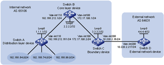
As shown in Figure 61, run EBGP between Switch C and Switch D, so the internal network and external network can communicate with each other.
In AS 65106, configure static routing between Switch A and Switch B, configure OSPF between Switch B and Switch C, and configure OSPF to redistribute static routes, so the devices in the internal network can communicate with each other.
Configure route summarization on Switch C so BGP advertises a summary route instead of the specific networks 192.168.64.0/24, 192.168.74.0/24, and 192.168.99.0/24 to Switch D.
Figure 61: Network diagram
Configuration procedure
Configure IP addresses for interfaces. (Details not shown.)
Configure static routing between Switch A and Switch B:
# Configure a default route with the next hop 192.168.212.1 on Switch A.
<SwitchA> system-view
[SwitchA] ip route-static 0.0.0.0 0 192.168.212.1
# Configure static routes to 192.168.64.0/24, 192.168.74.0/24, and 192.168.99.0/24 with the same next hop 192.168.212.161 on Switch B.
<SwitchB> system-view
[SwitchB] ip route-static 192.168.64.0 24 192.168.212.161
[SwitchB] ip route-static 192.168.74.0 24 192.168.212.161
[SwitchB] ip route-static 192.168.99.0 24 192.168.212.161
Configure OSPF between Switch B and Switch C and configure OSPF on Switch B to redistribute static routes:
# Configure OSPF to advertise the local network and enable OSPF to redistribute static routes on Switch B.
[SwitchB] ospf
[SwitchB-ospf-1] area 0
[SwitchB-ospf-1-area-0.0.0.0] network 172.17.100.0 0.0.0.255
[SwitchB-ospf-1-area-0.0.0.0] quit
[SwitchB-ospf-1] import-route static
[SwitchB-ospf-1] quit
# Configure OSPF to advertise the local networks on Switch C.
[SwitchC] ospf
[SwitchC-ospf-1] area 0
[SwitchC-ospf-1-area-0.0.0.0] network 172.17.100.0 0.0.0.255
[SwitchC-ospf-1-area-0.0.0.0] network 10.220.2.0 0.0.0.255
[SwitchC-ospf-1-area-0.0.0.0] quit
[SwitchC-ospf-1] quit
# Display the IP routing table on Switch C.
[SwitchC] display ip routing-table protocol ospf

Summary Count : 5

OSPF Routing table Status : <Active>
Summary Count : 3

Destination/Mask    Proto  Pre  Cost         NextHop         Interface
192.168.64.0/24     OSPF   150  1            172.17.100.1    Vlan100
192.168.74.0/24     OSPF   150  1            172.17.100.1    Vlan100
192.168.99.0/24     OSPF   150  1            172.17.100.1    Vlan100

OSPF Routing table Status : <Inactive>
Summary Count : 2

Destination/Mask    Proto  Pre  Cost         NextHop         Interface
10.220.2.0/24       OSPF   10   1            10.220.2.16     Vlan200
172.17.100.0/24     OSPF   10   1            172.17.100.2    Vlan100
The output shows that Switch C has learned routes to 192.168.64.0/24, 192.168.99.0/24, and 192.168.64.0/18 through OSPF.
Configure BGP between Switch C and Switch D and configure BGP on Switch C to redistribute OSPF routes:
# On Switch C, enable BGP, specify Switch D as an EBGP peer, and configure BGP to redistribute OSPF routes.
[SwitchC] bgp 65106
[SwitchC-bgp] router-id 3.3.3.3
[SwitchC-bgp] peer 10.220.2.217 as-number 64631
[SwitchC-bgp] address-family ipv4 unicast
[SwitchC-bgp-ipv4] peer 10.220.2.217 enable
[SwitchC-bgp-ipv4] import-route ospf
# Enable BGP, and configure Switch C as an EBGP peer on Switch D.
[SwitchD] bgp 64631
[SwitchD-bgp] router-id 4.4.4.4
[SwitchD-bgp] peer 10.220.2.16 as-number 65106
[SwitchD-bgp] address-family ipv4 unicast
[SwitchD-bgp-ipv4] peer 10.220.2.16 enable
[SwitchD-bgp-ipv4] quit
[SwitchD-bgp] quit
# Display the IP routing table on Switch D.
[SwitchD] display ip routing-table protocol bgp

Summary Count : 3

BGP Routing table Status : <Active>
Summary Count : 3

Destination/Mask    Proto  Pre  Cost         NextHop         Interface
192.168.64.0/24     BGP    255  1            10.220.2.16     Vlan200
192.168.74.0/24     BGP    255  1            10.220.2.16     Vlan200
192.168.99.0/24     BGP    255  1            10.220.2.16     Vlan200

BGP Routing table Status : <Inactive>
Summary Count : 0
The output shows that Switch D has learned routes to 192.168.64.0/24, 192.168.74.0/24, and 192.168.99.0/24 through BGP.
After the above configurations, ping hosts on networks 192.168.74.0/24, 192.168.99.0/24, and 192.168.64.0/18 from Switch D. The ping operations succeed.
Configure route summarization on Switch C to summarize 192.168.64.0/24, 192.168.74.0/24, and 192.168.99.0/24 into a single route 192.168.64.0/18 on Switch C, and disable advertisement of the specific routes.
[SwitchC-bgp-ipv4] aggregate 192.168.64.0 18 detail-suppressed
[SwitchC-bgp-ipv4] quit
[SwitchC-bgp] quit
Verifying the configuration
# Display IP routing table on Switch C.
[SwitchC] display ip routing-table | include 192.168
192.168.64.0/18     BGP    130  0            127.0.0.1       NULL0
192.168.64.0/24     OSPF   150  1            172.17.100.1    Vlan100
192.168.74.0/24     OSPF   150  1            172.17.100.1    Vlan100
192.168.99.0/24     OSPF   150  1            172.17.100.1    Vlan100
The output shows that Switch C has a summary route 192.168.64.0/18 with the output interface Null0.
# Display IP routing table on Switch D.
[SwitchD] display ip routing-table protocol bgp

Summary Count : 1

BGP Routing table Status : <Active>
Summary Count : 1

Destination/Mask    Proto  Pre  Cost         NextHop         Interface
192.168.64.0/18     BGP    255  0            10.220.2.16     Vlan200

BGP Routing table Status : <Inactive>
Summary Count : 0
The output shows that Switch D has only one route 192.168.64.0/18 to AS 65106.
After the above configurations, ping the hosts on networks 192.168.64.0/24, 192.168.74.0/24 and 192.168.99.0/24 from Switch D. The ping operations succeed.