Connecting the console cable
Before login through the console port or USB console port, connect the PC (or terminal) and the switch using the following methods accordingly:
Console port—Use the console cable to connect the serial port on the PC (or terminal) to the console port on the switch.
USB console port—Use the console cable to connect the USB port on the PC (or terminal) to the USB console port on the switch.
Introduction to console cables
Console cables connecting the console port on a switch and serial port on a PC or terminal
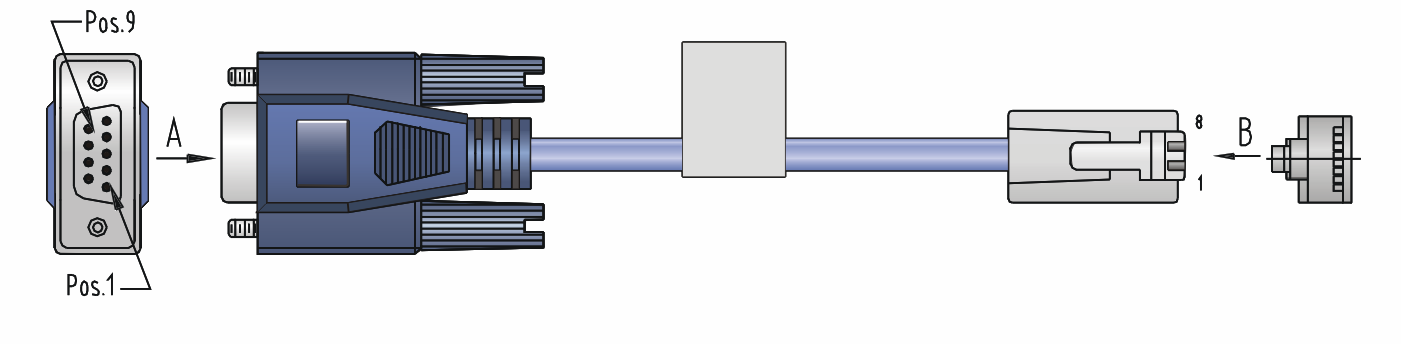
The console cable is an 8-core shielded cable, with a crimped RJ-45 connector for connecting to the console port of the switch, and a DB-9 female connector for connecting to the serial port on the console terminal.
Figure 34 shows the console cable and Table 9 shows its pinouts.
Figure 34: Console cable connecting the serial port and the console port
Table 9: Pinouts for the console cable connecting the serial port and the console port
RJ-45 pin | Signal | DB-9 pin | Signal |
|---|---|---|---|
1 | RTS | 8 | CTS |
2 | DTR | 6 | DSR |
3 | TXD | 2 | RXD |
4 | CD | 5 | SG |
5 | GND | 5 | SG |
6 | RXD | 3 | TXD |
7 | DSR | 4 | DTR |
8 | CTS | 7 | RTS |
Console cables connecting the USB console port on a switch and the USB port on a PC or terminal
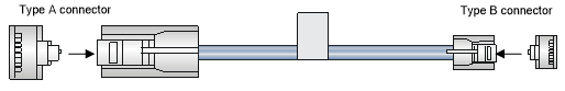
The console cable consists of one mini-USB A/B connector for connecting to the USB console port on the switch and one USB A connector for connecting to the USB port on the PC or terminal.
Figure 35 shows the console cable and Table 10 shows its pinouts.
Figure 35: Console cable connecting the USB port and the USB console port
Table 10: Pinouts for the console cable connecting the USB port and the USB console port
USB A pin | Signal | mini-USB A/B pin | Signal |
|---|---|---|---|
1 | VBUS | 1 | VBUS |
2 | D- | 2 | D- |
3 | D+ | 3 | D+ |
4 | ID(NC) | ||
4 | GND | 5 | GND |
Connection procedure
Figure 36: Connecting through the console port and the serial port
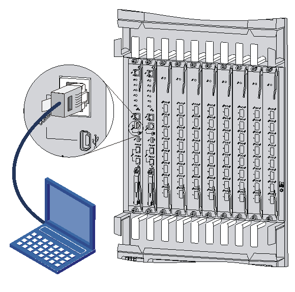
To connect the console cable through the console port:
Connect the DB-9 connector of the console cable to the serial port on a PC or terminal.
Connect the RJ-45 connector of the console cable to the console port on the MPU of the switch.
To connect the console cable through the USB console port:
Connect the USB-A connector of the console cable to the USB port on a PC or terminal.
Connect the mini-USB A/B connector of the console cable to the USB console port on the MPU of the switch.
![[NOTE: ]](images/note.png)
NOTE:
If two MPUs are installed on the switch, log in through the console port or USB console port on the active MPU (typically with a smaller slot number) for the first login.
When you remove the console cable, first disconnect the switch end, and then disconnect the PC end.