Connecting a DC power cord
![[CAUTION: ]](images/caution.png) | CAUTION: A plastic protection cover is installed in front of the terminal block to protect operators from being shocked. Remove the protection cover before connecting power cords and then install the protection cover promptly. | |
Eight pairs of wiring terminals (marked PSU1 through PSU8) are available on the DC terminal block of the 12508E/12518E. The wiring terminals correspond to the power modules. The power source provides power to the switch through the wiring terminals. If slot 1 is installed with a power module, the wiring terminals marked PSR1 or PSU1 must be connected to the power source with a DC power cord to make the power module operate correctly.
The 12508E-DC and 12518E-DC models adopt the PSE20KD1 DC power system.
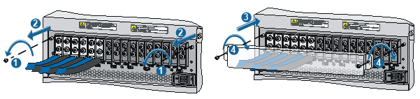
To connect the PSE20KD1 DC power cords:
Remove the screws from the power frame.
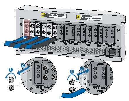
Secure the blue DC power cord to the NEG (–) terminal on the terminal block with screws using a Phillips screwdriver.
Secure the ring terminal of the black power cord to the RTN (+) terminal on the terminal block with screws using a Phillips screwdriver.
Figure 32: Connecting the DC power cords to terminals on the power supply
Connect the other end of the DC power cord to the power source:
Connect the other end of the black DC power cord to the RTN (+) terminal that provides power to the switch.
Connect the other end of the blue DC power cord to the –48V terminal that provides a power supply to the switch.
Install the protection cover:
Remove the screws on the DC power frame.
Install the protection cover on the wiring terminals.
Fasten the screws using a Phillips screwdriver.
Figure 33: Installing the protection cover