Cooling
Plan the installation site for adequate ventilation.
Leave at least 10 cm (3.94 in) of clearance around the air intake vents and exhaust vents.
Equip a good cooling system for the cabinet to install the switch.
Equip a good cooling system for the installation site.
Figure 2, and Figure 3 show the ventilation of the 12508E, and 12518E.
Figure 2: Airflow through a 12508E chassis
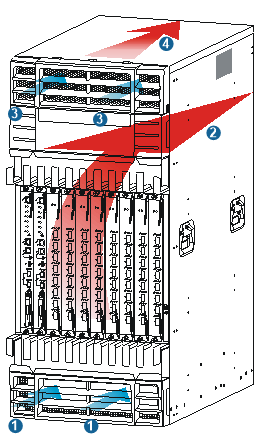
(1) Air intake direction of the chassis | (2) Air exhaust direction of the chassis |
(3) Air intake direction of the power supplies | (4) Air exhaust direction of the power supplies |
Figure 3: Airflow through a 12518E chassis
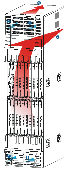
(1) Air intake direction of the chassis | (2) Air exhaust direction of the chassis |
(3) Air intake direction of the power supplies | (4) Air exhaust direction of the power supplies |