OSPFv3 NSR configuration example
Network requirements
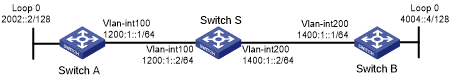
As shown in Figure 109, Switch S, Switch A, and Switch B belong to the same AS and OSPFv3 routing domain. Enable OSPFv3 NSR on Switch S to ensure correct routing when an active/standby switchover occurs on Switch S.
Figure 109: Network diagram
Configuration procedure
Configure IP addresses and subnet masks for interfaces on the switches. (Details not shown.)
Configure OSPFv3 on the switches to ensure that Switch S, Switch A, and Switch B can communicate with each other at Layer 3. (Details not shown.)
Configure OSPFv3:
# On Switch A, enable OSPFv3, and set the router ID to 1.1.1.1.
<SwitchA> system-view
[SwitchA] ospfv3 1
[SwitchA-ospfv3-1] router-id 1.1.1.1
[SwitchA-ospfv3-1] quit
[SwitchA] interface vlan-interface 100
[SwitchA-Vlan-interface100] ospfv3 1 area 1
[SwitchA-Vlan-interface100] quit
# On Switch B, enable OSPFv3, and set the router ID to 2.2.2.2.
<SwitchB> system-view
[SwitchB] ospfv3 1
[SwitchB-ospfv3-1] router-id 2.2.2.2
[SwitchB-ospfv3-1] quit
[SwitchB] interface vlan-interface 200
[SwitchB-Vlan-interface200] ospfv3 1 area 1
[SwitchB-Vlan-interface200] quit
# On Switch S, enable OSPFv3, set the router ID to 3.3.3.3, and enable NSR.
<SwitchS> system-view
[SwitchS] ospfv3 1
[SwitchS-ospfv3-1] router-id 3.3.3.3
[SwitchS-ospfv3-1] non-stop-routing
[SwitchS-ospfv3-1] quit
[SwitchS] interface vlan-interface 100
[SwitchS-Vlan-interface100] ospfv3 1 area 1
[SwitchS-Vlan-interface100] quit
[SwitchS] interface vlan-interface 200
[SwitchS-Vlan-interface200] ospfv3 1 area 1
[SwitchS-Vlan-interface200] quit
Verifying the configuration
# Verify the following:
When an active/standby switchover occurs on Switch S, the neighbor relationships and routing information on Switch A and Switch B have not changed. (Details not shown.)
The traffic from Switch A to Switch B has not been impacted. (Details not shown.)