BGP route summarization configuration example
Network requirements
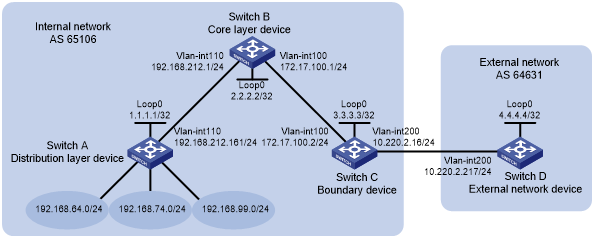
As shown in Figure 70, run EBGP between Switch C and Switch D, so the internal network and external network can communicate with each other.
In AS 65106, perform the following configurations so the devices in the internal network can communicate:
Configure static routing between Switch A and Switch B.
Configure OSPF between Switch B and Switch C.
Configure OSPF to redistribute static routes.
Configure route summarization on Switch C so BGP advertises a summary route instead of advertising routes to the 192.168.64.0/24, 192.168.74.0/24, and 192.168.99.0/24 networks to Switch D.
Figure 70: Network diagram
Configuration procedure
Configure IP addresses for interfaces. (Details not shown.)
Configure static routing between Switch A and Switch B:
# Configure a default route with the next hop 192.168.212.1 on Switch A.
<SwitchA> system-view
[SwitchA] ip route-static 0.0.0.0 0 192.168.212.1
# Configure static routes to 192.168.64.0/24, 192.168.74.0/24, and 192.168.99.0/24 with the same next hop 192.168.212.161 on Switch B.
<SwitchB> system-view
[SwitchB] ip route-static 192.168.64.0 24 192.168.212.161
[SwitchB] ip route-static 192.168.74.0 24 192.168.212.161
[SwitchB] ip route-static 192.168.99.0 24 192.168.212.161
Configure OSPF between Switch B and Switch C and configure OSPF on Switch B to redistribute static routes:
# Configure OSPF to advertise the local network and enable OSPF to redistribute static routes on Switch B.
[SwitchB] ospf
[SwitchB-ospf-1] area 0
[SwitchB-ospf-1-area-0.0.0.0] network 172.17.100.0 0.0.0.255
[SwitchB-ospf-1-area-0.0.0.0] quit
[SwitchB-ospf-1] import-route static
[SwitchB-ospf-1] quit
# Configure OSPF to advertise the local networks on Switch C.
[SwitchC] ospf
[SwitchC-ospf-1] area 0
[SwitchC-ospf-1-area-0.0.0.0] network 172.17.100.0 0.0.0.255
[SwitchC-ospf-1-area-0.0.0.0] network 10.220.2.0 0.0.0.255
[SwitchC-ospf-1-area-0.0.0.0] quit
[SwitchC-ospf-1] quit
# Display the IP routing table on Switch C.
[SwitchC] display ip routing-table protocol ospf

Summary count : 5

OSPF Routing table Status : <Active>
Summary count : 3

Destination/Mask    Proto  Pre  Cost         NextHop         Interface
192.168.64.0/24     OSPF   150  1            172.17.100.1    Vlan100
192.168.74.0/24     OSPF   150  1            172.17.100.1    Vlan100
192.168.99.0/24     OSPF   150  1            172.17.100.1    Vlan100

OSPF Routing table Status : <Inactive>
Summary count : 2

Destination/Mask    Proto  Pre  Cost         NextHop         Interface
10.220.2.0/24       OSPF   10   1            10.220.2.16     Vlan200
172.17.100.0/24     OSPF   10   1            172.17.100.2    Vlan100
The output shows that Switch C has learned routes to 192.168.64.0/24, 192.168.99.0/24, and 192.168.64.0/18 through OSPF.
Configure BGP between Switch C and Switch D and configure BGP on Switch C to redistribute OSPF routes:
# On Switch C, enable BGP, specify Switch D as an EBGP peer, and configure BGP to redistribute OSPF routes.
[SwitchC] bgp 65106
[SwitchC-bgp-default] router-id 3.3.3.3
[SwitchC-bgp-default] peer 10.220.2.217 as-number 64631
[SwitchC-bgp-default] address-family ipv4 unicast
[SwitchC-bgp-default-ipv4] peer 10.220.2.217 enable
[SwitchC-bgp-default-ipv4] import-route ospf
# Enable BGP, and configure Switch C as an EBGP peer on Switch D.
[SwitchD] bgp 64631
[SwitchD-bgp-default] router-id 4.4.4.4
[SwitchD-bgp-default] peer 10.220.2.16 as-number 65106
[SwitchD-bgp-default] address-family ipv4 unicast
[SwitchD-bgp-default-ipv4] peer 10.220.2.16 enable
[SwitchD-bgp-default-ipv4] quit
[SwitchD-bgp-default] quit
# Display the IP routing table on Switch D.
[SwitchD] display ip routing-table protocol bgp

Summary count : 3

BGP Routing table Status : <Active>
Summary count : 3

Destination/Mask    Proto  Pre  Cost         NextHop         Interface
192.168.64.0/24     BGP    255  1            10.220.2.16     Vlan200
192.168.74.0/24     BGP    255  1            10.220.2.16     Vlan200
192.168.99.0/24     BGP    255  1            10.220.2.16     Vlan200

BGP Routing table Status : <Inactive>
Summary count : 0
The output shows that Switch D has learned routes to 192.168.64.0/24, 192.168.74.0/24, and 192.168.99.0/24 through BGP.
# Verify that Switch D can ping hosts on networks 192.168.74.0/24, 192.168.99.0/24, and 192.168.64.0/18. (Details not shown.)
Configure route summarization on Switch C to summarize 192.168.64.0/24, 192.168.74.0/24, and 192.168.99.0/24 into a single route 192.168.64.0/18, and disable advertisement of specific routes.
[SwitchC-bgp-default-ipv4] aggregate 192.168.64.0 18 detail-suppressed
[SwitchC-bgp-default-ipv4] quit
[SwitchC-bgp-default] quit
Verifying the configuration
# Display IP routing table on Switch C.
[SwitchC] display ip routing-table | include 192.168
192.168.64.0/18     BGP    130  0            127.0.0.1       NULL0
192.168.64.0/24     OSPF   150  1            172.17.100.1    Vlan100
192.168.74.0/24     OSPF   150  1            172.17.100.1    Vlan100
192.168.99.0/24     OSPF   150  1            172.17.100.1    Vlan100
The output shows that Switch C has a summary route 192.168.64.0/18 with the output interface Null0.
# Display IP routing table on Switch D.
[SwitchD] display ip routing-table protocol bgp

Summary count : 1

BGP Routing table Status : <Active>
Summary count : 1

Destination/Mask    Proto  Pre  Cost         NextHop         Interface
192.168.64.0/18     BGP    255  0            10.220.2.16     Vlan200

BGP Routing table Status : <Inactive>
Summary count : 0
The output shows that Switch D has only one route 192.168.64.0/18 to AS 65106.
# Verify that Switch D can ping the hosts on networks 192.168.64.0/24, 192.168.74.0/24, and 192.168.99.0/24. (Details not shown.)