BFD for OSPF configuration example
Network requirements
As shown in Figure 33, run OSPF on Switch A, Switch B, and Switch C so that they are reachable to each other at the network layer.
When the link over which Switch A and Switch B communicate through a Layer 2 switch fails, BFD can quickly detect the failure and notify OSPF of the failure.
Switch A and Switch B then communicate through Switch C.
Figure 33: Network diagram
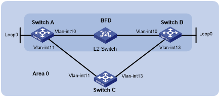
Table 9: Interface and IP address assignment
Device | Interface | IP address |
|---|---|---|
Switch A | Vlan-int10 | 192.168.0.102/24 |
Switch A | Vlan-int11 | 10.1.1.102/24 |
Switch A | Loop0 | 121.1.1.1/32 |
Switch B | Vlan-int10 | 192.168.0.100/24 |
Switch B | Vlan-int13 | 13.1.1.1/24 |
Switch B | Loop0 | 120.1.1.1/32 |
Switch C | Vlan-int11 | 10.1.1.100/24 |
Switch C | Vlan-int13 | 13.1.1.2/24 |
Configuration procedure
Configure IP addresses for interfaces. (Details not shown.)
Enable OSPF:
# Configure Switch A.
<SwitchA> system-view
[SwitchA] ospf
[SwitchA-ospf-1] area 0
[SwitchA-ospf-1-area-0.0.0.0] network 192.168.0.0 0.0.0.255
[SwitchA-ospf-1-area-0.0.0.0] network 10.1.1.0 0.0.0.255
[SwitchA-ospf-1-area-0.0.0.0] network 121.1.1.1 0.0.0.0
[SwitchA-ospf-1-area-0.0.0.0] quit
[SwitchA-ospf-1] quit
# Configure Switch B.
<SwitchB> system-view
[SwitchB] ospf
[SwitchB-ospf-1] area 0
[SwitchB-ospf-1-area-0.0.0.0] network 192.168.0.0 0.0.0.255
[SwitchB-ospf-1-area-0.0.0.0] network 13.1.1.0 0.0.0.255
[SwitchB-ospf-1-area-0.0.0.0] network 120.1.1.1 0.0.0.0
[SwitchB-ospf-1-area-0.0.0.0] quit
[SwitchB-ospf-1] quit
# Configure Switch C.
<SwitchC> system-view
[SwitchC] ospf
[SwitchC-ospf-1] area 0
[SwitchC-ospf-1-area-0.0.0.0] network 10.1.1.0 0.0.0.255
[SwitchC-ospf-1-area-0.0.0.0] network 13.1.1.0 0.0.0.255
[SwitchC-ospf-1-area-0.0.0.0] quit
[SwitchC-ospf-1] quit
Configure BFD:
# Enable BFD on Switch A and configure BFD parameters.
[SwitchA] bfd session init-mode active
[SwitchA] interface vlan-interface 10
[SwitchA-Vlan-interface10] ospf bfd enable
[SwitchA-Vlan-interface10] bfd min-transmit-interval 500
[SwitchA-Vlan-interface10] bfd min-receive-interval 500
[SwitchA-Vlan-interface10] bfd detect-multiplier 7
[SwitchA-Vlan-interface10] quit
# Enable BFD on Switch B and configure BFD parameters.
[SwitchB] bfd session init-mode active
[SwitchB] interface vlan-interface 10
[SwitchB-Vlan-interface10] ospf bfd enable
[SwitchB-Vlan-interface10] bfd min-transmit-interval 500
[SwitchB-Vlan-interface10] bfd min-receive-interval 500
[SwitchB-Vlan-interface10] bfd detect-multiplier 6
[SwitchB-Vlan-interface10] quit
Verifying the configuration
# Display the BFD information on Switch A.
<SwitchA> display bfd session

 Total Session Num: 1     Up Session Num: 1     Init Mode: Active

 IPv4 Session Working Under Ctrl Mode:

 LD/RD          SourceAddr      DestAddr        State    Holdtime    Interface
 3/1            192.168.0.102   192.168.0.100   Up       1700ms      Vlan10
# Display routes destined for 120.1.1.1/32 on Switch A.
<SwitchA> display ip routing-table 120.1.1.1 verbose

Summary Count : 1

Destination: 120.1.1.1/32
   Protocol: O_INTRA
 Process ID: 1
  SubProtID: 0x1                     Age: 04h20m37s
       Cost: 1                Preference: 10
      IpPre: N/A              QosLocalID: N/A
        Tag: 0                     State: Active Adv
  OrigTblID: 0x0                 OrigVrf: default-vrf
    TableID: 0x2                  OrigAs: 0
      NibID: 0x26000002           LastAs: 0
     AttrID: 0xffffffff         Neighbor: 0.0.0.0
      Flags: 0x1008c         OrigNextHop: 192.168.0.100
      Label: NULL            RealNextHop: 192.168.0.100
    BkLabel: NULL              BkNextHop: N/A
  Tunnel ID: Invalid           Interface: Vlan-interface10
BkTunnel ID: Invalid         BkInterface: N/A
   FtnIndex: 0x0             TrafficIndex: N/A
  Connector: N/A
The output shows that Switch A communicates with Switch B through VLAN-interface 10. Then the link over VLAN-interface 10 fails.
# Display routes destined for 120.1.1.1/32 on Switch A.
<SwitchA> display ip routing-table 120.1.1.1 verbose

Summary Count : 1

Destination: 120.1.1.1/32
   Protocol: O_INTRA
 Process ID: 1
  SubProtID: 0x1                     Age: 04h20m37s
       Cost: 2                Preference: 10
      IpPre: N/A              QosLocalID: N/A
        Tag: 0                     State: Active Adv
  OrigTblID: 0x0                 OrigVrf: default-vrf
    TableID: 0x2                  OrigAs: 0
      NibID: 0x26000002           LastAs: 0
     AttrID: 0xffffffff         Neighbor: 0.0.0.0
      Flags: 0x1008c         OrigNextHop: 10.1.1.100
      Label: NULL            RealNextHop: 10.1.1.100
    BkLabel: NULL              BkNextHop: N/A
  Tunnel ID: Invalid           Interface: Vlan-interface11
BkTunnel ID: Invalid         BkInterface: N/A
   FtnIndex: 0x0            TrafficIndex: N/A
  Connector: N/A
The output shows that Switch A communicates with Switch B through VLAN-interface 11.