OSPF NSR configuration example
Network requirements
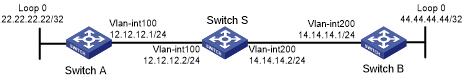
As shown in Figure 32, Switch S, Switch A, and Switch B belong to the same OSPF routing domain. Enable OSPF NSR on Switch S to ensure correct routing when an active/standby switchover occurs on Switch S.
Figure 32: Network diagram
Configuration procedure
Configure IP addresses and subnet masks for interfaces on the switches. (Details not shown.)
Configure OSPF on the switches to ensure the following: (Details not shown.)
Switch S, Switch A, and Switch B can communicate with each other at Layer 3.
Dynamic route update can be implemented among them with OSPF.
Enable OSPF NSR on Switch S.
<SwitchS> system-view
[SwitchS] ospf 100
[SwitchS-ospf-100] non-stop-routing
[SwitchS-ospf-100] quit
Verifying the configuration
# Perform an active/standby switchover on Switch S.
[SwitchS] placement reoptimize
Predicted changes to the placement
Program                           Current location       New location
---------------------------------------------------------------------
lb                                0/0                    0/0
lsm                               0/0                    0/0
slsp                              0/0                    0/0
rib6                              0/0                    0/0
routepolicy                       0/0                    0/0
rib                               0/0                    0/0
staticroute6                      0/0                    0/0
staticroute                       0/0                    0/0
eviisis                           0/0                    0/0
ospf                              0/0                    1/0
Continue? [y/n]:y
Re-optimization of the placement start. You will be notified on completion
Re-optimization of the placement complete. Use 'display placement' to view the new placement
# During the switchover period, display OSPF neighbors on Switch A to verify the neighbor relationship between Switch A and Switch S.
<SwitchA> display ospf peer

          OSPF Process 1 with Router ID 2.2.2.1
               Neighbor Brief Information

 Area: 0.0.0.0
 Router ID       Address         Pri Dead-Time  State             Interface
 3.3.3.1         12.12.12.2      1   37         Full/BDR          Vlan100
# Display OSPF routes on Switch A to verify if Switch A has a route to the loopback interface on Switch B.
<SwitchA> display ospf routing

          OSPF Process 1 with Router ID 2.2.2.1
                   Routing Table

                Topology base (MTID 0)

 Routing for network
 Destination        Cost     Type    NextHop         AdvRouter       Area
 44.44.44.44/32     2        Stub    12.12.12.2      4.4.4.1         0.0.0.0
 14.14.14.0/24      2        Transit 12.12.12.2      4.4.4.1         0.0.0.0
 22.22.22.22/32     0        Stub    22.22.22.22     2.2.2.1         0.0.0.0
 12.12.12.0/24      1        Transit 12.12.12.1      2.2.2.1         0.0.0.0

 Total nets: 4
 Intra area: 4  Inter area: 0  ASE: 0  NSSA: 0
# Display OSPF neighbors on Switch B to verify the neighbor relationship between Switch B and Switch S.
<SwitchB> display ospf peer

          OSPF Process 1 with Router ID 4.4.4.1
               Neighbor Brief Information

 Area: 0.0.0.0
 Router ID       Address         Pri Dead-Time  State             Interface
 3.3.3.1         14.14.14.2      1   39         Full/BDR          Vlan200
# Display OSPF routes on Switch B to verify if Switch B has a route to the loopback interface on Switch A.
<SwitchB> display ospf routing

          OSPF Process 1 with Router ID 4.4.4.1
                   Routing Table

                Topology base (MTID 0)

 Routing for network
 Destination        Cost     Type    NextHop         AdvRouter       Area
 44.44.44.44/32     0        Stub    44.44.44.44     4.4.4.1         0.0.0.0
 14.14.14.0/24      1        Transit 14.14.14.1      4.4.4.1         0.0.0.0
 22.22.22.22/32     2        Stub    14.14.14.2      2.2.2.1         0.0.0.0
 12.12.12.0/24      2        Transit 14.14.14.2      2.2.2.1         0.0.0.0

 Total nets: 4
 Intra area: 4  Inter area: 0  ASE: 0  NSSA: 0
The output shows the following when an active/standby switchover occurs on Switch S:
The neighbor relationships and routing information on Switch A and Switch B have not changed.
The traffic from Switch A to Switch B has not been impacted.