OSPF stub area configuration example
Network requirements
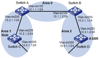
As shown in Figure 27:
Enable OSPF on all switches, and split the AS into three areas.
Configure Switch A and Switch B as ABRs to forward routing information between areas.
Configure Switch D as the ASBR to redistribute static routes.
Configure Area 1 as a stub area to reduce advertised LSAs without influencing reachability.
Figure 27: Network diagram
Configuration procedure
Configure IP addresses for interfaces. (Details not shown.)
Enable OSPF (see "Basic OSPF configuration example").
Configure route redistribution:
# Configure Switch D to redistribute static routes.
<SwitchD> system-view
[SwitchD] ip route-static 3.1.2.1 24 10.5.1.2
[SwitchD] ospf
[SwitchD-ospf-1] import-route static
[SwitchD-ospf-1] quit
# Display ABR/ASBR information on Switch C.
<SwitchC> display ospf abr-asbr

          OSPF Process 1 with Router ID 10.4.1.1
                  Routing Table to ABR and ASBR


                Topology base (MTID 0)
 Type        Destination     Area            Cost  Nexthop         RtType
 Intra       10.2.1.1        0.0.0.1         3     10.2.1.1        ABR
 Inter       10.5.1.1        0.0.0.1         7     10.2.1.1        ASBR
# Display OSPF routing table on Switch C.
<SwitchC> display ospf routing

          OSPF Process 1 with Router ID 10.4.1.1
                   Routing Table

                Topology base (MTID 0)

 Routing for network
 Destination        Cost     Type    NextHop         AdvRouter       Area
 10.2.1.0/24        3        Transit 0.0.0.0         10.2.1.1        0.0.0.1
 10.3.1.0/24        7        Inter   10.2.1.1        10.2.1.1        0.0.0.1
 10.4.1.0/24        3        Stub    10.4.1.1        10.4.1.1        0.0.0.1
 10.5.1.0/24        17       Inter   10.2.1.1        10.2.1.1        0.0.0.1
 10.1.1.0/24        5        Inter   10.2.1.1        10.2.1.1        0.0.0.1

 Routing for ASEs
 Destination        Cost     Type    Tag         NextHop         AdvRouter
 3.1.2.0/24         1        Type2   1           10.2.1.1        10.5.1.1

 Total nets: 6
 Intra area: 2  Inter area: 3  ASE: 1  NSSA: 0
The output shows that Switch C's routing table contains an AS external route.
Configure Area 1 as a stub area:
# Configure Switch A.
<SwitchA> system-view
[SwitchA] ospf
[SwitchA-ospf-1] area 1
[SwitchA-ospf-1-area-0.0.0.1] stub
[SwitchA-ospf-1-area-0.0.0.1] quit
[SwitchA-ospf-1] quit
# Configure Switch C.
<SwitchC> system-view
[SwitchC] ospf
[SwitchC-ospf-1] area 1
[SwitchC-ospf-1-area-0.0.0.1] stub
[SwitchC-ospf-1-area-0.0.0.1] quit
[SwitchC-ospf-1] quit
# Display OSPF routing information on Switch C
[SwitchC] display ospf routing

          OSPF Process 1 with Router ID 10.4.1.1
                   Routing Table

                Topology base (MTID 0)

 Routing for network
 Destination        Cost     Type    NextHop         AdvRouter       Area
 0.0.0.0/0          4        Inter   10.2.1.1        10.2.1.1        0.0.0.1
 10.2.1.0/24        3        Transit 0.0.0.0         10.2.1.1        0.0.0.1
 10.3.1.0/24        7        Inter   10.2.1.1        10.2.1.1        0.0.0.1
 10.4.1.0/24        3        Stub    10.4.1.1        10.4.1.1        0.0.0.1
 10.5.1.0/24        17       Inter   10.2.1.1        10.2.1.1        0.0.0.1
 10.1.1.0/24        5        Inter   10.2.1.1        10.2.1.1        0.0.0.1

 Total nets: 6
 Intra area: 2  Inter area: 4  ASE: 0  NSSA: 0
The output shows that a default route replaces the AS external route.
# Configure Area 1 as a totally stub area.
[SwitchA] ospf
[SwitchA-ospf-1] area 1
[SwitchA-ospf-1-area-0.0.0.1] stub no-summary
[SwitchA-ospf-1-area-0.0.0.1] quit
[SwitchA-ospf-1] quit
# Display OSPF routing information on Switch C.
[SwitchC] display ospf routing

          OSPF Process 1 with Router ID 10.4.1.1
                   Routing Table

                Topology base (MTID 0)

 Routing for network
 Destination        Cost     Type    NextHop         AdvRouter       Area
 0.0.0.0/0          4        Inter   10.2.1.1        10.2.1.1        0.0.0.1
 10.2.1.0/24        3        Transit 0.0.0.0         10.4.1.1        0.0.0.1
 10.4.1.0/24        3        Stub    10.4.1.1        10.4.1.1        0.0.0.1

 Total nets: 3
 Intra area: 2  Inter area: 1  ASE: 0  NSSA: 0
The output shows that inter-area routes are removed, and only one external route (a default route) exists on Switch C.