OSPF route summarization configuration example
Network requirements
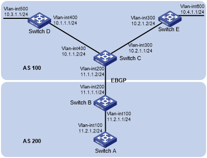
As shown in Figure 26:
Configure OSPF on Switch A and Switch B in AS 200.
Configure OSPF on Switch C, Switch D, and Switch E in AS 100.
Configure an EBGP connection between Switch B and Switch C. Configure Switch B and Switch C to redistribute OSPF routes and direct routes into BGP and BGP routes into OSPF.
Configure Switch B to advertise only summary route 10.0.0.0/8 to Switch A.
Figure 26: Network diagram
Configuration procedure
Configure IP addresses for interfaces. (Details not shown.)
Enable OSPF:
# Configure Switch A.
<SwitchA> system-view
[SwitchA] router id 11.2.1.2
[SwitchA] ospf
[SwitchA-ospf-1] area 0
[SwitchA-ospf-1-area-0.0.0.0] network 11.2.1.0 0.0.0.255
[SwitchA-ospf-1-area-0.0.0.0] quit
[SwitchA-ospf-1] quit
# Configure Switch B.
<SwitchB> system-view
[SwitchB] router id 11.2.1.1
[SwitchB] ospf
[SwitchB-ospf-1] area 0
[SwitchB-ospf-1-area-0.0.0.0] network 11.2.1.0 0.0.0.255
[SwitchB-ospf-1-area-0.0.0.0] quit
[SwitchB-ospf-1] quit
# Configure Switch C.
<SwitchC> system-view
[SwitchC] router id 11.1.1.2
[SwitchC] ospf
[SwitchC-ospf-1] area 0
[SwitchC-ospf-1-area-0.0.0.0] network 10.1.1.0 0.0.0.255
[SwitchC-ospf-1-area-0.0.0.0] network 10.2.1.0 0.0.0.255
[SwitchC-ospf-1-area-0.0.0.0] quit
[SwitchC-ospf-1] quit
# Configure Switch D.
<SwitchD> system-view
[SwitchD] router id 10.3.1.1
[SwitchD] ospf
[SwitchD-ospf-1] area 0
[SwitchD-ospf-1-area-0.0.0.0] network 10.1.1.0 0.0.0.255
[SwitchD-ospf-1-area-0.0.0.0] network 10.3.1.0 0.0.0.255
[SwitchD-ospf-1-area-0.0.0.0] quit
[SwitchD-ospf-1] quit
# Configure Switch E.
<SwitchE> system-view
[SwitchE] router id 10.4.1.1
[SwitchE] ospf
[SwitchE-ospf-1] area 0
[SwitchE-ospf-1-area-0.0.0.0] network 10.2.1.0 0.0.0.255
[SwitchE-ospf-1-area-0.0.0.0] network 10.4.1.0 0.0.0.255
[SwitchE-ospf-1-area-0.0.0.0] quit
[SwitchE-ospf-1] quit
Configure BGP to redistribute OSPF routes and direct routes:
# Configure Switch B.
[SwitchB] bgp 200
[SwitchB-bgp] peer 11.1.1.2 as 100
[SwitchB-bgp] address-family ipv4 unicast
[SwitchB-bgp-ipv4] import-route ospf
[SwitchB-bgp-ipv4] import-route direct
[SwitchB-bgp ipv4] quit
[SwitchB-bgp] quit
# Configure Switch C.
[SwitchC] bgp 100
[SwitchC-bgp] peer 11.1.1.1 as 200
[SwitchC-bgp] address-family ipv4 unicast
[SwitchC-bgp-ipv4] import-route ospf
[SwitchC-bgp-ipv4]import-route direct
[SwitchC-bgp-ipv4] quit
[SwitchC-bgp] quit
Configure Switch B and Switch C to redistribute BGP routes into OSPF:
# Configure OSPF to redistribute routes from BGP on Switch B.
[SwitchB] ospf
[SwitchB-ospf-1] import-route bgp
# Configure OSPF to redistribute routes from BGP on Switch C.
[SwitchC] ospf
[SwitchC-ospf-1] import-route bgp
# Display the OSPF routing table on Switch A.
[SwitchA] display ip routing-table

         Destinations : 16        Routes : 16

Destination/Mask    Proto  Pre  Cost         NextHop         Interface

0.0.0.0/32          Direct 0    0            127.0.0.1       InLoop0
10.1.1.0/24         O_ASE2 150  1            11.2.1.1        Vlan100
10.2.1.0/24         O_ASE2 150  1            11.2.1.1        Vlan100
10.3.1.0/24         O_ASE2 150  1            11.2.1.1        Vlan100
10.4.1.0/24         O_ASE2 150  1            11.2.1.1        Vlan100
11.2.1.0/24         Direct 0    0            11.2.1.2        Vlan100
11.2.1.0/32         Direct 0    0            11.2.1.2        Vlan100
11.2.1.2/32         Direct 0    0            127.0.0.1       InLoop0
11.2.1.255/32       Direct 0    0            11.2.1.2        Vlan100
127.0.0.0/8         Direct 0    0            127.0.0.1       InLoop0
127.0.0.0/32        Direct 0    0            127.0.0.1       InLoop0
127.0.0.1/32        Direct 0    0            127.0.0.1       InLoop0
127.255.255.255/32  Direct 0    0            127.0.0.1       InLoop0
224.0.0.0/4         Direct 0    0            0.0.0.0         NULL0
224.0.0.0/24        Direct 0    0            0.0.0.0         NULL0
255.255.255.255/32  Direct 0    0            127.0.0.1       InLoop0
Configure route summarization:
# Configure route summarization on Switch B to advertise a summary route 10.0.0.0/8.
[SwitchB-ospf-1] asbr-summary 10.0.0.0 8
# Display the IP routing table on Switch A.
[SwitchA] display ip routing-table

         Destinations : 13        Routes : 13

Destination/Mask    Proto  Pre  Cost         NextHop         Interface
0.0.0.0/32          Direct 0    0            127.0.0.1       InLoop0
10.0.0.0/8          O_ASE2 150  2            11.2.1.1        Vlan100
11.2.1.0/24         Direct 0    0            11.2.1.2        Vlan100
11.2.1.0/32         Direct 0    0            11.2.1.2        Vlan100
11.2.1.2/32         Direct 0    0            127.0.0.1       InLoop0
11.2.1.255/32       Direct 0    0            11.2.1.2        Vlan100
127.0.0.0/8         Direct 0    0            127.0.0.1       InLoop0
127.0.0.0/32        Direct 0    0            127.0.0.1       InLoop0
127.0.0.1/32        Direct 0    0            127.0.0.1       InLoop0
127.255.255.255/32  Direct 0    0            127.0.0.1       InLoop0
224.0.0.0/4         Direct 0    0            0.0.0.0         NULL0
224.0.0.0/24        Direct 0    0            0.0.0.0         NULL0
255.255.255.255/32  Direct 0    0            127.0.0.1       InLoop0
The output shows that routes 10.1.1.0/24, 10.2.1.0/24, 10.3.1.0/24 and 10.4.1.0/24 are summarized into a single route 10.0.0.0/8.