Configuring BFD for RIP (single hop echo detection for a specific destination)
Network requirements
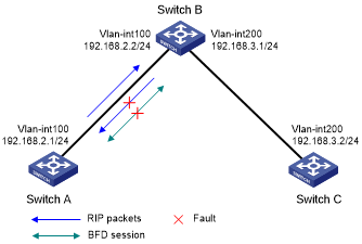
As shown in Figure 14, VLAN-interface 100 of Switch A and Switch B runs RIP process 1. VLAN-interface 200 of Switch B and Switch C runs RIP process 1.
Configure a static route destined for 100.1.1.0/24 and enable static route redistribution into RIP on both Switch A and Switch C. This allows Switch B to learn two routes destined for 100.1.1.0/24 through VLAN-interface 100 and VLAN-interface 200. The route redistributed from Switch A has a smaller cost than that redistributed from Switch C, so Switch B uses the route through VLAN-interface 200.
Enable BFD for RIP on VLAN-interface 100 of Switch A, and specify VLAN-interface 100 of Switch B as the destination. When a unidirectional link occurs between Switch A and Switch B, BFD can quickly detect the link failure and notify RIP. Switch B then deletes the neighbor relationship and the route information learned on VLAN-interface 100. It does not receive or send any packets from VLAN-interface 100. When the route learned from Switch A ages out, Switch B uses the route destined for 100.1.1.1 24 through VLAN-interface 200.
Figure 14: Network diagram
Configuration procedure
Configure IP addresses for interfaces. (Details not shown.)
Configure basic RIP and enable BFD on the interfaces:
# Configure Switch A.
<SwitchA> system-view
[SwitchA] rip 1
[SwitchA-rip-1] network 192.168.2.0
[SwitchA-rip-1] import-route static
[SwitchA-rip-1] quit
[SwitchA] interface vlan-interface 100
[SwitchA-Vlan-interface100] rip bfd enable destination 192.168.2.2
[SwitchA-Vlan-interface100] quit
# Configure Switch B.
<SwitchB> system-view
[SwitchB] rip 1
[SwitchB-rip-1] network 192.168.2.0
[SwitchB-rip-1] network 192.168.3.0
[SwitchB-rip-1] quit
# Configure Switch C.
<SwitchC> system-view
[SwitchC] rip 1
[SwitchC-rip-1] network 192.168.3.0
[SwitchC-rip-1] import-route static cost 3
[SwitchC-rip-1] quit
Configure BFD parameters on VLAN-interface 100 of Switch A.
[SwitchA] bfd echo-source-ip 11.11.11.11
[SwitchA] interface vlan-interface 100
[SwitchA-Vlan-interface100] bfd min-echo-receive-interval 500
[SwitchA-Vlan-interface100] return
Configure static routes:
# Configure a static route on Switch A.
[SwitchA] ip route-static 100.1.1.0 24 null 0
# Configure a static route on Switch C.
[SwitchA] ip route-static 100.1.1.0 24 null 0
Verifying the configuration
# Display BFD session information on Switch A.
<SwitchA> display bfd session

 Total Session Num: 1     Up Session Num: 1     Init Mode: Active

 IPv4 session working under Echo mode:

 LD             SourceAddr      DestAddr        State    Holdtime    Interface
 3              192.168.2.1     192.168.2.2     Up       2000ms      vlan100
# Display routes destined for 100.1.1.0/24 on Switch B.
<SwitchB> display ip routing-table 100.1.1.0 24 verbose

Summary Count : 1

Destination: 100.1.1.0/24
   Protocol: RIP
 Process ID: 1
  SubProtID: 0x1                     Age: 00h02m47s
       Cost: 1                Preference: 100
      IpPre: N/A              QosLocalID: N/A
        Tag: 0                     State: Active Adv
  OrigTblID: 0x0                 OrigVrf: default-vrf
    TableID: 0x2                  OrigAs: 0
      NibID: 0x12000002           LastAs: 0
     AttrID: 0xffffffff         Neighbor: 192.168.2.1
      Flags: 0x1008c         OrigNextHop: 192.168.2.1
      Label: NULL            RealNextHop: 192.168.2.1
    BkLabel: NULL              BkNextHop: N/A
  Tunnel ID: Invalid           Interface: vlan-interface 100
BkTunnel ID: Invalid         BkInterface: N/A
   FtnIndex: 0x0            TrafficIndex: N/A
  Connector: N/A
# Display routes destined for 100.1.1.0/24 on Switch B when the link between Switch A and Switch B fails.
<SwitchB> display ip routing-table 100.1.1.0 24 verbose

Summary Count : 1

Destination: 100.1.1.0/24
   Protocol: RIP
 Process ID: 1
  SubProtID: 0x1                     Age: 00h21m23s
       Cost: 4                Preference: 100
      IpPre: N/A              QosLocalID: N/A
        Tag: 0                     State: Active Adv
  OrigTblID: 0x0                 OrigVrf: default-vrf
    TableID: 0x2                  OrigAs: 0
      NibID: 0x12000002           LastAs: 0
     AttrID: 0xffffffff         Neighbor: 192.168.3.2
      Flags: 0x1008c         OrigNextHop: 192.168.3.2
      Label: NULL            RealNextHop: 192.168.3.2
    BkLabel: NULL              BkNextHop: N/A
  Tunnel ID: Invalid           Interface: vlan-interface 200
BkTunnel ID: Invalid         BkInterface: N/A
   FtnIndex: 0x0            TrafficIndex: N/A
  Connector: N/A