Configuring BFD for RIP (single-hop echo detection for a directly connected neighbor)
Network requirements
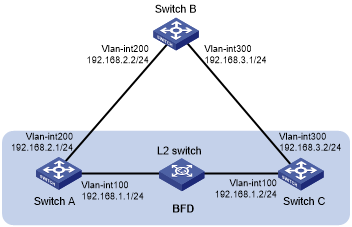
As shown in Figure 13, VLAN-interface 100 of Switch A and Switch C runs RIP process 1. VLAN-interface 200 of Switch A runs RIP process 2. VLAN-interface 300 of Switch C and VLAN-interface 200 and VLAN-interface 300 of Switch B run RIP process 1.
Configure a static route destined for 100.1.1.1/24 and enable static route redistribution into RIP on Switch C. This allows Switch A to learn two routes destined for 100.1.1.1/24 through VLAN-interface 100 and VLAN-interface 200 respectively, and uses the one through VLAN-interface 100.
Enable BFD for RIP on VLAN-interface 100 of Switch A. When the link over VLAN-interface 100 fails, BFD can quickly detect the failure and notify RIP. RIP deletes the neighbor relationship and route information learned on VLAN-interface 100, and uses the route destined for 100.1.1.1 24 through VLAN-interface 200.
Figure 13: Network diagram
Configuration procedure
Configure IP addresses for interfaces. (Details not shown.)
Configure basic RIP:
# Configure Switch A.
<SwitchA> system-view
[SwitchA] rip 1
[SwitchA-rip-1] version 2
[SwitchA-rip-1] undo summary
[SwitchA-rip-1] network 192.168.1.0
[SwitchA-rip-1] quit
[SwitchA] interface vlan-interface 100
[SwitchA-Vlan-interface100] rip bfd enable
[SwitchA-Vlan-interface100] quit
[SwitchA] rip 2
[SwitchA-rip-2] version 2
[SwitchA-rip-2] undo summary
[SwitchA-rip-2] network 192.168.2.0
[SwitchA-rip-2] quit
# Configure Switch B.
<SwitchB> system-view
[SwitchB] rip 1
[SwitchB-rip-1] version 2
[SwitchB-rip-1] undo summary
[SwitchB-rip-1] network 192.168.2.0
[SwitchB-rip-1] network 192.168.3.0
[SwitchB-rip-1] quit
# Configure Switch C.
<SwitchC> system-view
[SwitchC] rip 1
[SwitchC-rip-1] version 2
[SwitchC-rip-1] undo summary
[SwitchC-rip-1] network 192.168.1.0
[SwitchC-rip-1] network 192.168.3.0
[SwitchC-rip-1] import-route static
[SwitchC-rip-1] quit
Configure BFD parameters on VLAN-interface 100 of Switch A.
[SwitchA] bfd echo-source-ip 11.11.11.11
[SwitchA] interface vlan-interface 100
[SwitchA-Vlan-interface100] bfd min-transmit-interval 500
[SwitchA-Vlan-interface100] bfd min-receive-interval 500
[SwitchA-Vlan-interface100] bfd detect-multiplier 7
[SwitchA-Vlan-interface100] quit
[SwitchA] quit
Configure a static route on Switch C.
[SwitchC] ip route-static 120.1.1.1 24 null 0
Verifying the configuration
# Display the BFD session information on Switch A.
<SwitchA> display bfd session

 Total Session Num: 1     Up Session Num: 1     Init Mode: Active

 IPv4 Session Working Under Echo Mode:

 LD          SourceAddr      DestAddr        State    Holdtime    Interface
 4            192.168.1.1     192.168.1.2     Up       2000ms      Vlan100
# Display RIP routes destined for 120.1.1.0/24 on Switch A.
<SwitchA> display ip routing-table 120.1.1.0 24

Summary count : 1

Destination/Mask   Proto   Pre Cost        NextHop         Interface
120.1.1.0/24       RIP     100 1           192.168.1.2     Vlan-interface100
The output shows that Switch A communicates with Switch C through VLAN-interface 100. Then the link over VLAN-interface 100 fails.
# Display RIP routes destined for 120.1.1.0/24 on Switch A.
<SwitchA> display ip routing-table 120.1.1.0 24

Summary count : 1

Destination/Mask   Proto   Pre Cost        NextHop         Interface
120.1.1.0/24       RIP     100 1           192.168.2.2     Vlan-interface200
The output shows that Switch A communicates with Switch C through VLAN-interface 200.