Configuration example for L2TP multi-domain application
Network requirements
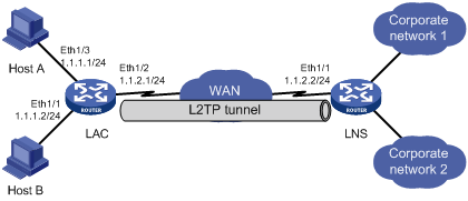
As shown in Figure 99, multiple enterprises share an LNS and use the same tunnel name for the LAC end. Users of different enterprises access their corporate servers through L2TP VPDNs.
Host A is a user from enterprise 1, which has the domain name aaa.net.
Host B is a user from enterprise 2, which has the domain name bbb.net.
Figure 99: Network diagram
Configuration procedure
Configure the LAC:
In this example, Ethernet 1/1 and Ethernet 1/3 on the LAC are both user access interfaces. The IP address of Ethernet 1/2, through which the LAC connects to the tunnel, is 1.1.2.1. The IP address of Ethernet 1/1, through which the LNS connects to the tunnel, is 1.1.2.2.
# Create two local users, set the passwords, and enable the PPP service.
<LAC> system-view
[LAC] local-user vpdn1
[LAC-luser-vpdn1] password simple 11111
[LAC-luser-vpdn1] service-type ppp
[LAC-luser-vpdn1] quit
[LAC] local-user vpdn2
[LAC-luser-vpdn2] password simple 22222
[LAC-luser-vpdn2] service-type ppp
[LAC-luser-vpdn2] quit
# Configure local authentication for the users.
[LAC] domain aaa.net
[LAC-isp-aaa.net] authentication ppp local
[LAC-isp-aaa.net] quit
[LAC] domain bbb.net
[LAC-isp-bbb.net] authentication ppp local
[LAC-isp-bbb.net] quit
# Configure PPPoE servers on interface Ethernet 1/1 and Ethernet 1/3.
[LAC] interface ethernet 1/3
[LAC-Ethernet1/3] pppoe-server bind virtual-template 100
[LAC-Ethernet1/3] quit
[LAC] interface ethernet 1/1
[LAC-Ethernet1/1] pppoe-server bind virtual-template 101
[LAC-Ethernet1/1] quit
# Configure an IP address for interface Ethernet 1/2.
[LAC] interface ethernet 1/2
[LAC-Ethernet1/2] ip address 1.1.2.1 255.255.255.0
[LAC-Ethernet1/2] quit
# Create the VT interfaces and configure CHAP authentication.
[LAC] interface virtual-template 100
[LAC-Virtual-Template100] ppp authentication-mode chap domain aaa.net
[LAC-Virtual-Template100] quit
[LAC] interface virtual-template 101
[LAC-Virtual-Template101] ppp authentication-mode chap domain bbb.net
[LAC-Virtual-Template101] quit
# Create two L2TP groups and configure the related attributes.
[LAC] l2tp enable
[LAC] l2tp-group 1
[LAC-l2tp1] tunnel name LAC-1
[LAC-l2tp1] start l2tp ip 1.1.2.2 domain aaa.net
[LAC-l2tp1] quit
[LAC] l2tp-group 2
[LAC-l2tp2] tunnel name LAC-1
[LAC-l2tp2] start l2tp ip 1.1.2.2 domain bbb.net
# Enable the tunnel authentication and specify a tunnel authentication key.
[LAC-l2tp2] tunnel authentication
[LAC-l2tp2] tunnel password simple 12345
[LAC-l2tp2] quit
[LAC] l2tp-group 1
[LAC-l2tp1] tunnel authentication
[LAC-l2tp1] tunnel password simple 12345
Configure the LNS:
# Enable L2TP.
<LNS> system-view
[LNS] l2tp enable
# Enable L2TP for VPNs.
[LNS] l2tpmoreexam enable
# Create two local users, set the passwords, and enable the PPP service.
[LNS] local-user vpdn1
[LNS-luser-vpdn1] password simple 11111
[LNS-luser-vpdn1] service-type ppp
[LNS-luser-vpdn1] quit
[LNS] local-user vpdn2
[LNS-luser-vpdn2] password simple 22222
[LNS-luser-vpdn2] service-type ppp
[LNS-luser-vpdn2] quit
# Specify the IP address of Ethernet 1/1, through which the LNS connects to the tunnel, as 1.1.2.2.
[LNS] interface ethernet 1/1
[LNS-Ethernet1/1] ip address 1.1.2.2 255.255.255.0
[LNS-Ethernet1/1] quit
# Create two address pools.
[LNS] domain aaa.net
[LNS-isp-aaa.net] authentication ppp local
[LNS-isp-aaa.net] ip pool 1 10.0.1.10 10.0.1.100
[LNS-isp-aaa.net] quit
[LNS] domain bbb.net
[LNS-isp-bbb.net] authentication ppp local
[LNS-isp-bbb.net] ip pool 1 10.0.2.10 10.0.2.100
[LNS-isp-bbb.net] quit
# Create two VT interfaces.
[LNS] interface virtual-template 1
[LNS-Virtual-Template1] ip address 10.0.1.1 255.255.255.0
[LNS-Virtual-Template1] remote address pool 1
[LNS-Virtual-Template1] ppp authentication-mode chap domain aaa.net
[LNS-Virtual-Template1] quit
[LNS] interface virtual-template 2
[LNS-Virtual-Template2] ip address 10.0.2.1 255.255.255.0
[LNS-Virtual-Template2] remote address pool 1
[LNS-Virtual-Template2] ppp authentication-mode chap domain bbb.net
[LNS-Virtual-Template2] quit
# Create two L2TP groups.
[LNS] l2tp-group 3
[LNS-l2tp3] tunnel name LNS
[LNS-l2tp3] tunnel authentication
[LNS-l2tp3] allow l2tp virtual-template 1 remote LAC-1 domain aaa.net
[LNS-l2tp3] tunnel password simple 12345
[LNS-l2tp3] quit
[LNS] l2tp-group 4
[LNS-l2tp4] tunnel name LNS
[LNS-l2tp4] tunnel authentication
[LNS-l2tp4] allow l2tp virtual-template 2 remote LAC-1 domain bbb.net
[LNS-l2tp4] tunnel password simple 12345
If RADIUS authentication is required on the LNS, modify the AAA configurations as needed. For AAA configuration details, see HPE FlexNetwork MSR Router Series Comware 5 Security Configuration Guide.
Configure the users:
Create a dial-up connection on each host:
On Host A, enter vpdn1@aaa.net as the username and 11111 as the password in the dial-up terminal window.
On Host B, enter vpdn2@aaa.net as the username and 22222 as the password in the dial-up terminal window.
Verify the configuration:
# After Host A establishes a dial-up connection with enterprise 1, Host A obtains the IP address 10.0.1.10 and can ping the private address of the LNS (10.0.1.1).
# After Host B establishes a dial-up connection with enterprise 2, Host B obtains the IP address 10.0.2.10 and can ping the private address of the LNS (10.0.2.1).
# On the LNS, use the display l2tp session command to check the established L2TP sessions.
[LNS-l2tp1] display l2tp session
 Total session = 2

 LocalSID  RemoteSID  LocalTID
  17345     4351       1
  23914     10923      2
# On the LNS, use the display l2tp tunnel command to check the established L2TP tunnels.
[LNS-l2tp1] display l2tp tunnel
 Total tunnel = 2

 LocalTID RemoteTID RemoteAddress    Port   Sessions RemoteName
 1        1         1.1.2.1          1701   1        LAC-1
 2        2         1.1.2.1          1701   1        LAC-1