Configuring DLSw with VLAN support
Network requirements
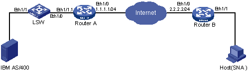
As shown in Figure 80, Ethernet 1/1 of the Ethernet switch is connected with an IBM host, Ethernet 1/0 of the switch is connected with Router A, and Ethernet 1/1 of Router B is connected with an SNA host. Perform the following configuration so the IBM host can communicate with the SNA host over the Internet:
Assign Ethernet 1/1 to VLAN 2, configure Ethernet 1/0 as a trunk port and assign it to VLAN 2.
Configure a sub-interface Ethernet 1/1.1 on Ethernet 1/1 of Router A and assign this sub-interface to VLAN 2.
Configure DLSw on Router A and Router B.
Figure 80: Network diagram
Configuration procedure
Configure Router A:
# Configure interfaces on Router A to make sure that the local DLSw peer 1.1.1.1 and remote peer 2.2.2.2 can reach each other. (Details not shown.)
# Configure DLSw on Router A.
[RouterA] bridge enable
[RouterA] bridge 1 enable
[RouterA] dlsw local 1.1.1.1
[RouterA] dlsw remote 2.2.2.2
[RouterA] dlsw bridge-set 1
[RouterA] interface ethernet 1/1.1
[RouterA-Ethernet1/1.1] bridge-set 1
Configure Router B:
# Configure interfaces on Router B to make sure that the local DLSw peer 2.2.2.2 and remote peer 1.1.1.1 can reach each other. (Details not shown.)
# Configure DLSw on Router B.
<RouterB> system-view
[RouterB] bridge enable
[RouterB] bridge 1 enable
[RouterB] dlsw local 2.2.2.2
[RouterB] dlsw remote 1.1.1.1
[RouterB] dlsw bridge-set 1
[RouterB] interface ethernet 1/1
[RouterB-Ethernet1/1] bridge-set 1
Configure LSW:
# Create VLAN 2, and assign Ethernet 1/1 to it.
<LSW> system-view
[LSW] vlan 2
[LSW-vlan2] port ethernet 1/1
[LSW-vlan2] quit
# Set Ethernet 1/0 to trunk mode and allow VLAN 2 to pass.
[LSW] interface ethernet1/0
[LSW-Ethernet1/0] port link-type trunk
[LSW-Ethernet1/0] port trunk permit vlan 2