Configuring DLSw for SDLC-to-LAN remote media translation
Network requirements
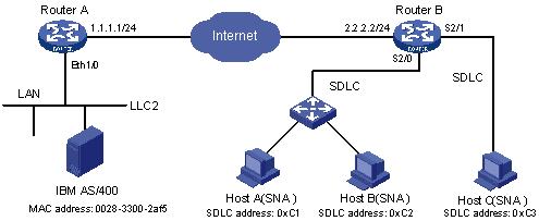
As shown in Figure 79, Host A and Host B are PU2.0 nodes (ATM), and Host C is a PU2.1 node (OS2). Configure DLSw on Router A and Router B, using NRZ encoding on the port connected with the multiplexer and NRZI encoding on the port connected with Host C, so the IBM host can communicate with all the SNA PCs over the Internet.
Figure 79: Network diagram
Configuration procedure
Configure Router A:
# Configure interfaces on Router A to make sure that the local DLSw peer 1.1.1.1 and remote peer 2.2.2.2 can reach each other. (Details not shown.)
# Configure DLSw on Router A.
<RouterA> system-view
[RouterA] bridge enable
[RouterA] bridge 1 enable
[RouterA] dlsw local 1.1.1.1
[RouterA] dlsw remote 2.2.2.2
[RouterA] dlsw bridge-set 1
[RouterA] interface ethernet 1/0
[RouterA-Ethernet1/0] bridge-set 1
Configure Router B:
# Configure interfaces on Router B to make sure that the local DLSw peer 2.2.2.2 and remote peer 1.1.1.1 can reach each other. (Details not shown.)
# Configure DLSw on Router B.
<RouterB> system-view
[RouterB] dlsw local 2.2.2.2
[RouterB] dlsw remote 1.1.1.1
[RouterB] interface serial 2/0
[RouterB-Serial2/0] link-protocol sdlc
[RouterB-Serial2/0] sdlc enable dlsw
[RouterB-Serial2/0] sdlc status primary
[RouterB-Serial2/0] sdlc mac-map local 0000-1234-5600
[RouterB-Serial2/0] sdlc controller c1
[RouterB-Serial2/0] sdlc xid c1 03e00001
[RouterB-Serial2/0] sdlc mac-map remote 0014-cc00-54af c1
[RouterB-Serial2/0] sdlc controller c2
[RouterB-Serial2/0] sdlc xid c2 03e00002
[RouterB-Serial2/0] sdlc mac-map remote 0014-cc00-54af c2
[RouterB-Serial2/0] baudrate 9600
[RouterB-Serial2/0] quit
[RouterB] interface serial 2/1
[RouterB-Serial2/1] link-protocol sdlc
[RouterB-Serial2/1] baudrate 9600
[RouterB-Serial2/1] code nrzi
[RouterB-Serial2/1] sdlc status primary
[RouterB-Serial2/1] sdlc mac-map local 0000-2222-0000
[RouterB-Serial2/1] sdlc controller c3
[RouterB-Serial2/1] sdlc mac-map remote 0014-cc00-54af c3
[RouterB-Serial2/1] sdlc enable dlsw
[RouterB-Serial2/1] quit
# If the local and remote networks are stable, configure the following commands to save the polling process.
[RouterB] dlsw reachable mac-exclusivity
[RouterB] dlsw reachable-cache 0014-cc00-54af remote 1.1.1.1
In the configuration file of router B, the MAC address in the sdlc mac-map remote and dlsw reachable-cache commands is the MAC address of the Ethernet card of the AS/400 device, which is connected to Router A. Because an Ethernet MAC address appears in the reverse bit order of a Token-Ring MAC address, bit order reversal is required in MAC address configuration (for example, a MAC address 0028-3300-2af5 appears to be 0014-cc00-54af after bit order reversal). If the peer end is Token-Ring, bit order reversal is not required.