OSPF is a link-state routing protocol applied to routers grouped into OSPF areas identified by the routing configuration on each routing switch. The protocol uses LSAs transmitted by each router to update neighboring routers regarding its interfaces and the routes available through those interfaces. Each routing switch in an area also maintains a link-state database (LSDB) that describes the area topology. (All routers in a given OSPF area have identical LSDBs.) The routing switches used to connect areas to each other flood summary link LSAs and external link LSAs to neighboring OSPF areas to update them regarding available routes. Through this means, each OSPF router determines the shortest path between itself and a desired destination router in the same OSPF domain (AS.)Routed traffic in an OSPF AS is classified as one of the following:
-
Intra-area traffic
-
Inter-area traffic
-
External traffic
The switches support the following types of LSAs, which are described in RFCs 2328 and 3101:
OSPF LSA types
| LSA type | LSA name | Use |
|---|---|---|
| 1 | Router link | Describes the state of each interface on a router for a given area. Not propagated to backbone area. |
| 2 | Network link | Describes the OSPF routers in a given network. Not propagated to backbone area. |
| 3 | Summary link | Describes the route to networks in another OSPF area of the same AS. Propagated through backbone area to other areas. |
| 4 | Autonomous System (AS) summary link | Describes the route to an ASBR in an OSPF normal or backbone area of the same AS. Propagated through backbone area to other areas. |
| 5 | AS external link |
Describes the route to a destination in another AS (external route.) Originated by ASBR in normal or backbone areas of an AS and propagates through backbone area to other normal areas. For injection into an NSSA, ABR converts type-5 LSAs to a type-7 LSA advertising the default route (0.0.0.0/0.) |
| 7 | AS external link in an NSSA |
Describes the route to a destination in another AS (external route.) Originated by ASBR in NSSA. ABR converts type-7 LSAs to type-5 LSAs for injection into the backbone area. |
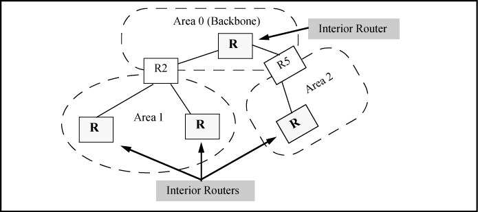
This type of OSPF router belongs to only one area. Interior routers flood type-1 LSAs to all routers in the same area and maintain identical LSDBs. In Example of interior routers, routers R1, R3, R4, and R6 are all interior routers because all of their links are to other routers in the same area.
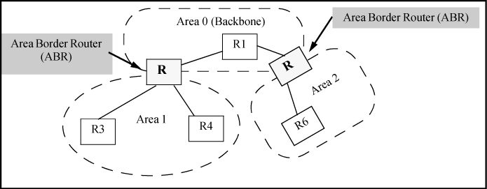
This type of OSPF router has membership in multiple areas . ABRs are used to connect the various areas in an AS to the backbone area for that AS. Multiple ABRs can be used to connect a given area to the backbone, and a given ABR can belong to multiple areas other than the backbone.
An ABR maintains a separate LSDB for each area to which it belongs. (All routers within the same area have identical LSDBs.) The ABR is responsible for flooding summary LSAs between its border areas. You can reduce summary LSA flooding by configuring area ranges. An area range enables you to assign an aggregate address to a range of IP addresses. This aggregate address is advertised instead of all the individual addresses it represents. You can assign up to eight ranges in an OSPF area. In Example of deploying ABRs to connect areas to the backbone, routers R2 and R5 are ABRs because they both have membership in more than one area.
This type of OSPF router runs multiple interior gateway protocols and serves as a gateway to other autonomous systems operating with interior gateway protocols. The ASBR imports and translates different protocol routes into OSPF through redistribution. ASBRs can be used in backbone areas, normal areas, and NSSAs, but not in stub areas. For more details on redistribution and configuration examples, see Enabling route redistribution.
In an OSPF network having two or more routers, one router is elected to serve as the DR and another router to act as the BDR. All other routers in the area forward their routing information to the DR and BDR, and the DR forwards this information to all of the routers in the network. This minimizes the amount of repetitive information that is forwarded on the network by eliminating the need for each individual router in the area to forward its routing information to all other routers in the network. If the area includes multiple networks, each network elects its own DR and BDR.
In an OSPF network with no DR and no BDR, the neighboring router with the highest priority is elected the DR, and the router with the next highest priority is elected the BDR. If the DR goes off-line, the BDR automatically becomes the DR, and the router with the next highest priority then becomes the new BDR. If multiple HPE routing switches on the same OSPF network are declaring themselves DRs, both priority and router ID are used to select the DR and BDRs.
Priority is configurable by using the vlan command at the interface level. You can use this parameter to help bias one router as the DR. For more information, see Changing priority per-interface. If two neighbors share the same priority, the router with the highest router ID is designated the DR. The router with the next highest router ID is designated the BDR.vid ip ospf priority 0-255
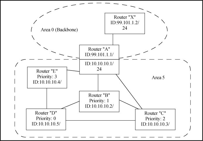
For example, in Example of DRs in an OSPF area, the DR and BDR for 10.10.10.0 network in area 5 are determined as follows:
| Router A | Priority: 0 | Cannot become a DR or BDR |
| Router B | Priority: 1 | DR for the 10.10.10.0 network |
| Router C | Priority: 2 | BDR for the 10.10.10.0 network |
| Router D | Priority: 3 | Cannot become a DR or BDR |
| Router E | Priority: 4 | Becomes the new BDR if router B becomes unavailable and router C becomes the new DR |
To learn the router priority on an interface, use the show ip ospf interface command and check the Pri setting under OSPF interface configuration.
|
|
|
![[NOTE: ]](images/note.gif) |
NOTE: By default, the router ID is typically the lowest-numbered IP address or the lowest-numbered (user-configured) loopback interface configured on the device. For more information or to change the router ID, see Changing the router ID. If multiple networks exist in the same OSPF area, the recommended approach is to ensure that each network uses a different router as its DR. Otherwise, if a router is a DR for more than one network, latency in the router could increase because of the increased traffic load resulting from multiple DR assignments. |
|
|
When only one router on an OSPF network claims the DR role despite neighboring routers with higher priorities or router IDs, this router remains the DR. This is also true for BDRs.
The DR and BDR election process is performed when one of the following events occurs:
-
Interface is in a waiting state and the wait time expires
-
Interface is in a waiting state and a hello packet is received that addresses the BDR
-
Change in the neighbor state occurs, such as:
-
Neighbor state transitions from 2 or higher
-
Communication to a neighbor is lost
-
Neighbor declares itself to be the DR or BDR for the first time
-