Example: Configuring an IPv4 over IPv4 GRE tunnel
Network configuration
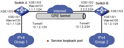
As shown in Figure 98, Group 1 and Group 2 are two private IPv4 networks. The two networks both use private network addresses and belong to the same VPN. Establish a GRE tunnel between Switch A and Switch B to interconnect the two private IPv4 networks Group 1 and Group 2.
Figure 98: Network diagram
Procedure
![[IMPORTANT: ]](images/important.png) | IMPORTANT: By default, interfaces on the devices are disabled (in ADM or Administratively Down state). To have an interface operate, you must use the undo shutdown command to enable that interface. | |
Before performing the following configuration, configure an IP address for each interface, and make sure Switch A and Switch B can reach each other.
Configure Switch A:
# Create service loopback group 1, and configure the service type as tunnel.
<SwitchA> system-view
[SwitchA] service-loopback group 1 type tunnel
# Add port Ten-GigabitEthernet 1/0/3 to service loopback group 1.
[SwitchA] interface ten-gigabitethernet 1/0/3
[SwitchA-Ten-GigabitEthernet1/0/3] port service-loopback group 1
[SwitchA-Ten-GigabitEthernet1/0/3] quit
# Create a tunnel interface Tunnel 1, and specify the tunnel mode as GRE/IPv4.
[SwitchA] interface tunnel 1 mode gre
# Configure an IP address for the tunnel interface.
[SwitchA-Tunnel1] ip address 10.1.2.1 255.255.255.0
# Configure the source address of tunnel interface as the IP address of VLAN-interface 101 on Switch A.
[SwitchA-Tunnel1] source vlan-interface 101
# Configure the destination address of the tunnel interface as the IP address of VLAN-interface 101 on Switch B.
[SwitchA-Tunnel1] destination 2.2.2.2
[SwitchA-Tunnel1] quit
# Configure a static route from Switch A through the tunnel interface to Group 2.
[SwitchA] ip route-static 10.1.3.0 255.255.255.0 tunnel 1
Configure Switch B:
# Create service loopback group 1, and configure the service type as tunnel.
<SwitchB> system-view
[SwitchB] service-loopback group 1 type tunnel
# Add port Ten-GigabitEthernet 1/0/3 to service loopback group 1.
[SwitchB] interface ten-gigabitethernet 1/0/3
[SwitchB-Ten-GigabitEthernet1/0/3] port service-loopback group 1
[SwitchB-Ten-GigabitEthernet1/0/3] quit
# Create a tunnel interface Tunnel 1, and specify the tunnel mode as GRE/IPv4.
[SwitchB] interface tunnel 1 mode gre
# Configure an IP address for the tunnel interface.
[SwitchB-Tunnel1] ip address 10.1.2.2 255.255.255.0
# Configure the source address of tunnel interface as the IP address of VLAN-interface 101 on Switch B.
[SwitchB-Tunnel1] source vlan-interface 101
# Configure the destination address of the tunnel interface as the IP address of VLAN-interface 101 on Switch A.
[SwitchB-Tunnel1] destination 1.1.1.1
[SwitchB-Tunnel1] quit
# Configure a static route from Switch B through the tunnel interface to Group 1.
[SwitchB] ip route-static 10.1.1.0 255.255.255.0 Tunnel 1
Verifying the configuration
# Display tunnel interface information on Switch A.
[SwitchA] display interface tunnel 1
Tunnel1
Current state: UP
Line protocol state: UP
Description: Tunnel1 Interface
Bandwidth: 64kbps
Maximum transmission unit: 1476
Internet address: 10.1.2.1/24 (primary)
Tunnel source 1.1.1.1, destination 2.2.2.2
Tunnel keepalive disabled
Tunnel TTL 255
Tunnel protocol/transport GRE/IP
    GRE key disabled
    Checksumming of GRE packets disabled
Last clearing of counters: Never
Last 300 seconds input rate: 0 bytes/sec, 0 bits/sec, 0 packets/sec
Last 300 seconds output rate: 0 bytes/sec, 0 bits/sec, 0 packets/sec
Input: 0 packets, 0 bytes, 0 drops
Output: 0 packets, 0 bytes, 0 drops
# Display tunnel interface information on Switch B.
[SwitchB] display interface tunnel 1
Tunnel1
Current state: UP
Line protocol state: UP
Description: Tunnel1 Interface
Bandwidth: 64kbps
Maximum transmission unit: 1476
Internet address: 10.1.2.2/24 (primary)
Tunnel source 2.2.2.2, destination 1.1.1.1
Tunnel keepalive disabled
Tunnel TTL 255
Tunnel protocol/transport GRE/IP
    GRE key disabled
    Checksumming of GRE packets disabled
Last clearing of counters: Never
Last 300 seconds input rate: 0 bytes/sec, 0 bits/sec, 0 packets/sec
Last 300 seconds output rate: 0 bytes/sec, 0 bits/sec, 0 packets/sec
Input: 0 packets, 0 bytes, 0 drops
Output: 0 packets, 0 bytes, 0 drops
# From Switch B, ping the IP address of VLAN-interface 100 on Switch A.
[SwitchB] ping -a 10.1.3.1 10.1.1.1
Ping 10.1.1.1 (10.1.1.1) from 10.1.3.1: 56 data bytes, press CTRL_C to break
56 bytes from 10.1.1.1: icmp_seq=0 ttl=255 time=11.000 ms
56 bytes from 10.1.1.1: icmp_seq=1 ttl=255 time=1.000 ms
56 bytes from 10.1.1.1: icmp_seq=2 ttl=255 time=0.000 ms
56 bytes from 10.1.1.1: icmp_seq=3 ttl=255 time=0.000 ms
56 bytes from 10.1.1.1: icmp_seq=4 ttl=255 time=0.000 ms

--- Ping statistics for 10.1.1.1 ---
5 packet(s) transmitted, 5 packet(s) received, 0.0% packet loss
round-trip min/avg/max/std-dev = 0.000/2.400/11.000/4.317 ms
The output shows that Switch B can successfully ping Switch A.
