RIP interface additional metric configuration example
Network requirements
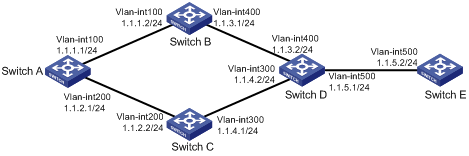
As shown in Figure 9, run RIPv2 on all the interfaces of Switch A, Switch B, Switch C, Switch D, and Switch E.
Switch A has two links to Switch D. The link from Switch B to Switch D is more stable than that from Switch C to Switch D. Configure an additional metric for RIP routes received from VLAN-interface 200 on Switch A so Switch A prefers route 1.1.5.0/24 learned from Switch B.
Figure 9: Network diagram
Configuration procedure
Configure IP addresses for interfaces. (Details not shown.)
Configure basic RIP:
# Configure Switch A.
<SwitchA> system-view
[SwitchA] rip 1
[SwitchA-rip-1] network 1.0.0.0
[SwitchA-rip-1] version 2
[SwitchA-rip-1] undo summary
[SwitchA-rip-1] quit
# Configure Switch B.
<SwitchB> system-view
[SwitchB] rip 1
[SwitchB-rip-1] network 1.0.0.0
[SwitchB-rip-1] version 2
[SwitchB-rip-1] undo summary
# Configure Switch C.
<SwitchC> system-view
[SwitchB] rip 1
[SwitchC-rip-1] network 1.0.0.0
[SwitchC-rip-1] version 2
[SwitchC-rip-1] undo summary
# Configure Switch D.
<SwitchD> system-view
[SwitchD] rip 1
[SwitchD-rip-1] network 1.0.0.0
[SwitchD-rip-1] version 2
[SwitchD-rip-1] undo summary
# Configure Switch E.
<SwitchE> system-view
[SwitchE] rip 1
[SwitchE-rip-1] network 1.0.0.0
[SwitchE-rip-1] version 2
[SwitchE-rip-1] undo summary
# Display all active routes in the RIP database on Switch A.
[SwitchA] display rip 1 database
   1.0.0.0/8, auto-summary
       1.1.1.0/24, cost 0, nexthop 1.1.1.1, RIP-interface
       1.1.2.0/24, cost 0, nexthop 1.1.2.1, RIP-interface
       1.1.3.0/24, cost 1, nexthop 1.1.1.2
       1.1.4.0/24, cost 1, nexthop 1.1.2.2
       1.1.5.0/24, cost 2, nexthop 1.1.1.2
       1.1.5.0/24, cost 2, nexthop 1.1.2.2
The output shows two RIP routes destined for network 1.1.5.0/24. The next hops of the routes are Switch B (1.1.1.2) and Switch C (1.1.2.2). The cost of the routes is 2.
Configure an additional metric for a RIP interface:
# Configure an inbound additional metric of 3 for RIP-enabled interface VLAN-interface 200 on Switch A.
[SwitchA] interface vlan-interface 200
[SwitchA-Vlan-interface200] rip metricin 3
# Display all active routes in the RIP database on Switch A.
[SwitchA-Vlan-interface200] display rip 1 database
   1.0.0.0/8, auto-summary
       1.1.1.0/24, cost 0, nexthop 1.1.1.1, RIP-interface
       1.1.2.0/24, cost 0, nexthop 1.1.2.1, RIP-interface
       1.1.3.0/24, cost 1, nexthop 1.1.1.2
       1.1.4.0/24, cost 2, nexthop 1.1.1.2
       1.1.5.0/24, cost 2, nexthop 1.1.1.2
The output shows that only one RIP route reaches network 1.1.5.0/24, with the next hop as Switch B (1.1.1.2) and a cost of 2.