Example: Configuring VRRP-Track-route management collaboration
Network configuration
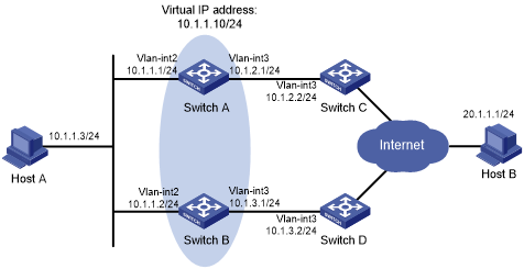
As shown in Figure 64:
Host A requires access to Host B. The default gateway of Host A is 10.1.1.10/24.
Switch A and Switch B belong to VRRP group 1. The virtual IP address of VRRP group 1 is 10.1.1.10.
BGP peer relationships are established between Switch A and Switch C and between Switch B and Switch D. Switch C and Switch D advertise the default route 0.0.0.0/0 to Switch A and Switch B.
Configure VRRP-Track-route management collaboration to meet the following requirements:
When Switch A operates correctly, Switch A forwards packets from Host A to Host B.
When VRRP detects the removal of the default route from the routing table of Switch A through route management, Switch B forwards packets from Host A to Host B.
Figure 64: Network diagram
Procedure
![[IMPORTANT: ]](images/important.png) | IMPORTANT: By default, interfaces on the device are disabled (in ADM or Administratively Down state). To have an interface operate, you must use the undo shutdown command to enable that interface. | |
Configure the IP address of each interface, as shown in Figure 64. (Details not shown.)
Establish an IBGP peer relationship between Switch A and Switch C, and configure Switch C to advertise the default route 0.0.0.0/0 to Switch A.
<SwitchA> system-view
[SwitchA] bgp 100
[SwitchA-bgp-default] peer 10.1.2.2 as-number 100
[SwitchA-bgp-default] address-family ipv4
[SwitchA-bgp-default-ipv4] peer 10.1.2.2 enable
<SwitchC> system-view
[SwitchC] bgp 100
[SwitchC-bgp-default] peer 10.1.2.1 as-number 100
[SwitchC-bgp-default] address-family ipv4
[SwitchC-bgp-default-ipv4] peer 10.1.2.1 enable
[SwitchC-bgp-default-ipv4] peer 10.1.2.1 default-route-advertise
[SwitchC-bgp-default-ipv4] quit
Configure Switch B and Switch D in the same way Switch A and Switch C are configured. (Details not shown.)
Configure Track and VRRP on Switch A:
# Configure track entry 1, and associate it with the default route 0.0.0.0/0.
[SwitchA] track 1 ip route 0.0.0.0 0.0.0.0 reachability
# Create VRRP group 1, and configure virtual IP address 10.1.1.10 for the group.
[SwitchA] interface vlan-interface 2
[SwitchA-Vlan-interface2] vrrp vrid 1 virtual-ip 10.1.1.10
# Set the priority of Switch A to 110 in VRRP group 1.
[SwitchA-Vlan-interface2] vrrp vrid 1 priority 110
# Associate VRRP group 1 with track entry 1 and decrease the Switch priority by 30 when the state of track entry 1 changes to negative.
[SwitchA-Vlan-interface2] vrrp vrid 1 track 1 priority reduced 30
[SwitchA-Vlan-interface2] quit
On Switch B, create VRRP group 1, and configure virtual IP address 10.1.1.10 for the group.
<SwitchB> system-view
[SwitchB] interface vlan-interface 2
[SwitchB-Vlan-interface2] vrrp vrid 1 virtual-ip 10.1.1.10
[SwitchB-Vlan-interface2] quit
Verifying the configuration
# Ping Host B from Host A to verify that Host B is reachable. (Details not shown.)
# Display detailed information about VRRP group 1 on Switch A.
[SwitchA] display vrrp verbose
IPv4 Virtual Router Information:
 Running Mode       : Standard
 Total number of virtual routers : 1
   Interface Vlan-interface2
     VRID             : 1               Adver Timer  : 100
     Admin Status     : Up              State        : Master
     Config Pri       : 110             Running Pri  : 110
     Preempt Mode     : Yes             Delay Time   : 0
     Auth Type        : None
     Virtual IP       : 10.1.1.10
     Virtual MAC      : 0000-5e00-0101
     Master IP        : 10.1.1.1
   VRRP Track Information:
     Track Object   : 1              State : Positive          Pri Reduced : 30
# Display detailed information about VRRP group 1 on Switch B.
[SwitchB] display vrrp verbose
IPv4 Virtual Router Information:
 Running Mode       : Standard
 Total number of virtual routers : 1
   Interface Vlan-interface2
     VRID             : 1               Adver Timer  : 100
     Admin Status     : Up              State        : Backup
     Config Pri       : 100             Running Pri  : 100
     Preempt Mode     : Yes             Delay Time   : 0
     Become Master    : 2200ms left
     Auth Type        : None
     Virtual IP       : 10.1.1.10
     Master IP        : 10.1.1.1
The output shows that in VRRP group 1, Switch A is the master and Switch B is a backup. Switch A forwards packets from Host A to Host B.
# Disable Switch C from exchanging routing information with Switch A so that the default route 0.0.0.0/0 is removed from the routing table of Switch A.
[SwitchC-bgp-default-ipv4] undo peer 10.1.2.1 enable
# Ping Host B from Host A to verify that Host B is reachable. (Details not shown.)
# Display detailed information about VRRP group 1 on Switch A.
[SwitchA] display vrrp verbose
IPv4 Virtual Router Information:
 Running Mode      : Standard
 Total number of virtual routers : 1
   Interface Vlan-interface2
     VRID             : 1               Adver Timer  : 100
     Admin Status     : Up              State        : Backup
     Config Pri       : 110             Running Pri  : 80
     Preempt Mode     : Yes             Delay Time   : 0
     Become Master    : 2200ms left
     Auth Type        : None
     Virtual IP       : 10.1.1.10
     Master IP        : 10.1.1.2
   VRRP Track Information:
     Track Object   : 1              State : Negative          Pri Reduced : 30
# Display detailed information about VRRP group 1 on Switch B.
[SwitchB] display vrrp verbose
IPv4 Virtual Router Information:
 Running Mode      : Standard
 Total number of virtual routers : 1
   Interface Vlan-interface2
     VRID             : 1               Adver Timer  : 100
     Admin Status     : Up              State        : Master
     Config Pri       : 100             Running Pri  : 100
     Preempt Mode     : Yes             Delay Time   : 0
     Auth Type        : None
     Virtual IP       : 10.1.1.10
     Virtual MAC      : 0000-5e00-0101
     Master IP        : 10.1.1.2
The output shows that Switch A becomes the backup, and Switch B becomes the master. Switch B forwards packets from Host A to Host B.