Example: Configuring multiple VRRP groups
Network configuration
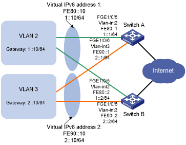
As shown in Figure 55, Switch A and Switch B form two VRRP groups. VRRP group 1 uses the virtual IPv6 addresses 1::10/64 and FE80::10 to provide gateway service for hosts in VLAN 2. VRRP group 2 uses the virtual IPv6 addresses 2::10/64 and FE90::10 to provide gateway service for hosts in VLAN 3.
From RA messages sent by the switches, hosts in VLAN 2 learn 1::10/64 as their default gateway. Hosts in VLAN 3 learn 2::10/64 as their default gateway.
Assign Switch A a higher priority than Switch B in VRRP group 1 but a lower priority in VRRP group 2. Traffic from VLAN 2 and VLAN 3 can then be distributed between the two switches. When one of the switches fails, the healthy switch provides gateway service for both VLANs.
Figure 55: Network diagram
Procedure
![[IMPORTANT: ]](images/important.png) | IMPORTANT: By default, interfaces on the device are disabled (in ADM or Administratively Down state). To have an interface operate, you must use the undo shutdown command to enable that interface. | |
Configure Switch A:
# Configure VLAN 2.
<SwitchA> system-view
[SwitchA] vlan 2
[SwitchA-vlan2] port fortygige 1/0/5
[SwitchA-vlan2] quit
[SwitchA] interface vlan-interface 2
[SwitchA-Vlan-interface2] ipv6 address fe80::1 link-local
[SwitchA-Vlan-interface2] ipv6 address 1::1 64
# Create VRRP group 1, and set its virtual IPv6 addresses to FE80::10 to 1::10.
[SwitchA-Vlan-interface2] vrrp ipv6 vrid 1 virtual-ip fe80::10 link-local
[SwitchA-Vlan-interface2] vrrp ipv6 vrid 1 virtual-ip 1::10
# Assign Switch A a higher priority than Switch B in VRRP group 1, so Switch A can become the master in the group.
[SwitchA-Vlan-interface2] vrrp ipv6 vrid 1 priority 110
# Enable Switch A to send RA messages, so hosts in VLAN 2 can learn the default gateway address.
[SwitchA-Vlan-interface2] undo ipv6 nd ra halt
[SwitchA-Vlan-interface2] quit
# Configure VLAN 3.
[SwitchA] vlan 3
[SwitchA-vlan3] port fortygige 1/0/6
[SwitchA-vlan3] quit
[SwitchA] interface vlan-interface 3
[SwitchA-Vlan-interface3] ipv6 address fe90::1 link-local
[SwitchA-Vlan-interface3] ipv6 address 2::1 64
# Create VRRP group 2, and set its virtual IPv6 addresses to FE90::10 and 2::10.
[SwitchA-Vlan-interface3] vrrp ipv6 vrid 2 virtual-ip fe90::10 link-local
[SwitchA-Vlan-interface3] vrrp ipv6 vrid 2 virtual-ip 2::10
# Enable Switch A to send RA messages, so hosts in VLAN 3 can learn the default gateway address.
[SwitchA-Vlan-interface3] undo ipv6 nd ra halt
Configure Switch B:
# Configure VLAN 2.
<SwitchB> system-view
[SwitchB-vlan2] port fortygige 1/0/5
[SwitchB-vlan2] quit
[SwitchB] interface vlan-interface 2
[SwitchB-Vlan-interface2] ipv6 address fe80::2 link-local
[SwitchB-Vlan-interface2] ipv6 address 1::2 64
# Create VRRP group 1, and set its virtual IPv6 addresses to FE80::10 and 1::10.
[SwitchB-Vlan-interface2] vrrp ipv6 vrid 1 virtual-ip fe80::10 link-local
[SwitchB-Vlan-interface2] vrrp ipv6 vrid 1 virtual-ip 1::10
# Enable Switch B to send RA messages, so hosts in VLAN 2 can learn the default gateway address.
[SwitchB-Vlan-interface2] undo ipv6 nd ra halt
[SwitchB-Vlan-interface2] quit
# Configure VLAN 3.
[SwitchB] vlan 3
[SwitchB-vlan3] port
[SwitchB-vlan3] quit
[SwitchB] interface vlan-interface 3
[SwitchB-Vlan-interface3] ipv6 address fe90::2 link-local
[SwitchB-Vlan-interface3] ipv6 address 2::2 64
# Create VRRP group 2, and set its virtual IPv6 addresses to FE90::10 and 2::10.
[SwitchB-Vlan-interface3] vrrp ipv6 vrid 2 virtual-ip fe90::10 link-local
[SwitchB-Vlan-interface3] vrrp ipv6 vrid 2 virtual-ip 2::10
# Assign Switch B a higher priority than Switch A in VRRP group 2, so Switch B can become the master in the group.
[SwitchB-Vlan-interface3] vrrp ipv6 vrid 2 priority 110
# Enable Switch B to send RA messages, so hosts in VLAN 3 can learn the default gateway address.
[SwitchB-Vlan-interface3] undo ipv6 nd ra halt
Verifying the configuration
# Display detailed information about the VRRP groups on Switch A.
[SwitchA-Vlan-interface3] display vrrp ipv6 verbose
IPv6 Virtual Router Information:
 Running Mode      : Standard
 Total number of virtual routers : 2
   Interface Vlan-interface2
     VRID             : 1                    Adver Timer  : 100
     Admin Status     : Up                   State        : Master
     Config Pri       : 110                  Running Pri  : 110
     Preempt Mode     : Yes                  Delay Time   : 0
     Auth Type        : None
     Virtual IP       : FE80::10
                        1::10
     Virtual MAC      : 0000-5e00-0201
     Master IP        : FE80::1

   Interface Vlan-interface3
     VRID             : 2                    Adver Timer  : 100
     Admin Status     : Up                   State        : Backup
     Config Pri       : 100                  Running Pri  : 100
     Preempt Mode     : Yes                  Delay Time   : 0
     Become Master    : 402ms left
     Auth Type        : None
     Virtual IP       : FE90::10
                        2::10
     Master IP        : FE90::2
# Display detailed information about the VRRP groups on Switch B.
[SwitchB-Vlan-interface3] display vrrp ipv6 verbose
IPv6 Virtual Router Information:
 Running Mode      : Standard
 Total number of virtual routers : 2
   Interface Vlan-interface2
     VRID             : 1                    Adver Timer  : 100
     Admin Status     : Up                   State        : Backup
     Config Pri       : 100                  Running Pri  : 100
     Preempt Mode     : Yes                  Delay Time   : 0
     Become Master    : 401ms left
     Auth Type        : None
     Virtual IP       : FE80::10
                        1::10
     Master IP        : FE80::1

   Interface Vlan-interface3
     VRID             : 2                    Adver Timer  : 100
     Admin Status     : Up                   State        : Master
     Config Pri       : 110                  Running Pri  : 110
     Preempt Mode     : Yes                  Delay Time   : 0
     Auth Type        : None
     Virtual IP       : FE90::10
                        2::10
     Virtual MAC      : 0000-5e00-0202
     Master IP        : FE90::2
The output shows the following information:
Switch A is operating as the master in VRRP group 1 to forward Internet traffic for hosts that use the default gateway 1::10/64.
Switch B is operating as the master in VRRP group 2 to forward Internet traffic for hosts that use the default gateway 2::10/64.