Example: Configuring Smart Link and Track collaboration
Network configuration
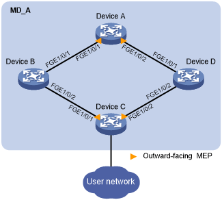
As shown in Figure 40:
Device A, Device B, Device C, and Device D form maintenance domain (MD) MD_A of level 5. Device C is a Smart Link device, and Device A, Device B, and Device D are associated devices. Traffic of VLANs 1 through 200 on Device C is dually uplinked to Device A by Device B and Device D.
Configure collaboration between Smart Link and the CC function of CFD through track entries to meet the following requirements:
Traffic of VLANs 1 through 100 is uplinked to Device A by Device C through FortyGigE 1/0/1 (primary port of smart link group 1).
Traffic of VLANs 101 through 200 is uplinked to Device A by Device C through FortyGigE 1/0/2 (primary port of smart link group 2).
When the link between Device C and Device A fails, traffic is quickly switched to the secondary port of each smart link group. After the fault is cleared, traffic is switched back to the primary ports.
For more information about CFD, see "Configuring CFD."
Figure 40: Network diagram
Procedure
![[IMPORTANT: ]](images/important.png) | IMPORTANT: By default, interfaces on the device are disabled (in ADM or Administratively Down state). To have an interface operate, you must use the undo shutdown command to enable that interface. | |
Configure Device A:
# Create VLAN 1 through VLAN 200.
<DeviceA> system-view
[DeviceA] vlan 1 to 200
# Configure FortyGigE 1/0/1 as a trunk port.
[DeviceA] interface fortygige 1/0/1
[DeviceA-FortyGigE1/0/1] port link-type trunk
# Assign the port to VLANs 1 through 200.
[DeviceA-FortyGigE1/0/1] port trunk permit vlan 1 to 200
# Enable flush message receiving and configure VLAN 10 and VLAN 110 as the receive control VLANs on the port.
[DeviceA-FortyGigE1/0/1] smart-link flush enable control-vlan 10 110
[DeviceA-FortyGigE1/0/1] quit
# Configure in the same way FortyGigE 1/0/1 is configured.
[DeviceA] interface fortygige 1/0/2
[DeviceA-] port link-type trunk
[DeviceA-FortyGigE1/0/2] port trunk permit vlan 1 to 200
[DeviceA-FortyGigE1/0/2] smart-link flush enable control-vlan 10 110
[DeviceA-FortyGigE1/0/2] quit
# Enable CFD and create MD MD_A of level 5.
[DeviceA] cfd enable
[DeviceA] cfd md MD_A level 5
# Create service instance 1 in which the MA name is based on the VLAN ID in MD_A and configure the MA to serve VLAN 10.
[DeviceA] cfd service-instance 1 ma-id vlan-based md MD_A vlan 10
# Create a MEP list in service instance 1, create outward-facing MEP 1002, and enable CCM sending in service instance 1 on FortyGigE 1/0/1.
[DeviceA] cfd meplist 1001 1002 service-instance 1
[DeviceA] interface fortygige 1/0/1
[DeviceA-FortyGigE1/0/1] cfd mep 1002 service-instance 1 outbound
[DeviceA-FortyGigE1/0/1] cfd cc service-instance 1 mep 1002 enable
[DeviceA-FortyGigE1/0/1] quit
# Create service instance 2 in which the MA name is based on the VLAN ID in MD_A and configure the MA to serve VLAN 110.
[DeviceA] cfd service-instance 2 ma-id vlan-based md MD_A vlan 110
# Create a MEP list in service instance 2, create outward-facing MEP 1002, and enable CCM sending in service instance 2 on FortyGigE 1/0/2.
[DeviceA] cfd meplist 2001 2002 service-instance 2
[DeviceA] interface fortygige 1/0/2
[DeviceA-FortyGigE1/0/2] cfd mep 2002 service-instance 2 outbound
[DeviceA-FortyGigE1/0/2] cfd cc service-instance 2 mep 2002 enable
[DeviceA-FortyGigE1/0/2] quit
Configure Device B:
# Create VLAN 1 through VLAN 200.
<DeviceB> system-view
[DeviceB] vlan 1 to 200
# Configure FortyGigE 1/0/1 as a trunk port.
[DeviceB] interface fortygige 1/0/1
[DeviceB-] port link-type trunk
# Assign the port to VLANs 1 through 200.
[DeviceB-FortyGigE1/0/1] port trunk permit vlan 1 to 200
# Enable flush message receiving and configure VLAN 10 and VLAN 110 as the receive control VLANs on the port.
[DeviceB-FortyGigE1/0/1] smart-link flush enable control-vlan 10 110
[DeviceB-FortyGigE1/0/1] quit
# Configure FortyGigE 1/0/2 as a trunk port.
[DeviceB] interface fortygige 1/0/2
[DeviceB-FortyGigE1/0/2] port link-type trunk
# Assign the port to VLANs 1 through 200.
[DeviceB-FortyGigE1/0/2] port trunk permit vlan 1 to 200
# Disable the spanning tree feature on the port.
[DeviceB-] undo stp enable
# Enable flush message receiving and configure VLAN 10 and VLAN 110 as the receive control VLANs on the port.
[DeviceB-FortyGigE1/0/2] smart-link flush enable control-vlan 10 110
[DeviceB-FortyGigE1/0/2] quit
Configure Device C:
# Create VLAN 1 through VLAN 200.
<DeviceC> system-view
[DeviceC] vlan 1 to 200
# Map VLANs 1 through 100 to MSTI 1 and VLANs 101 through 200 to MSTI 2.
[DeviceC] stp region-configuration
[DeviceC-mst-region] instance 1 vlan 1 to 100
[DeviceC-mst-region] instance 2 vlan 101 to 200
# Activate the MST region configuration.
[DeviceC-mst-region] active region-configuration
[DeviceC-mst-region] quit
# Shut down FortyGigE 1/0/1.
[DeviceC] interface fortygige 1/0/1
[DeviceC-FortyGigE1/0/1] shutdown
# Disable the spanning tree feature on the port.
[DeviceC-FortyGigE1/0/1] undo stp enable
# Configure the port as a trunk port.
[DeviceC-FortyGigE1/0/1] port link-type trunk
# Assign the port to VLANs 1 through 200.
[DeviceC-FortyGigE1/0/1] port trunk permit vlan 1 to 200
[DeviceC-FortyGigE1/0/1] quit
# Configure FortyGigE 1/0/2 in the same way FortyGigE 1/0/1 is configured.
[DeviceC] interface fortygige 1/0/2
[DeviceC-FortyGigE1/0/2] shutdown
[DeviceC-FortyGigE1/0/2] undo stp enable
[DeviceC-FortyGigE1/0/2] port link-type trunk
[DeviceC-FortyGigE1/0/2] port trunk permit vlan 1 to 200
[DeviceC-FortyGigE1/0/2] quit
# Create smart link group 1, and configure all VLANs mapped to MSTI 1 as the protected VLANs for smart link group 1.
[DeviceC] smart-link group 1
[DeviceC-smlk-group1] protected-vlan reference-instance 1
# Configure FortyGigE 1/0/1 as the primary port and as the secondary port for smart link group 1.
[DeviceC-smlk-group1] port fortygige 1/0/1 primary
[DeviceC-smlk-group1] port  secondary
# Enable role preemption in smart link group 1, enable flush message sending, and configure VLAN 10 as the transmit control VLAN.
[DeviceC-smlk-group1] preemption mode role
[DeviceC-smlk-group1] flush enable control-vlan 10
[DeviceC-smlk-group1] quit
# Create smart link group 2, and configure all VLANs mapped to MSTI 2 as the protected VLANs for smart link group 2.
[DeviceC] smart-link group 2
[DeviceC-smlk-group2] protected-vlan reference-instance 2
# Configure as the secondary port and FortyGigE 1/0/2 as the primary port for smart link group 2.
[DeviceC-smlk-group2] port fortygige 1/0/2 primary
[DeviceC-smlk-group2] port fortygige 1/0/1 secondary
# Enable role preemption in smart link group 2, enable flush message sending, and configure VLAN 110 as the transmit control VLAN.
[DeviceC-smlk-group2] preemption mode role
[DeviceC-smlk-group2] flush enable control-vlan 110
[DeviceC-smlk-group2] quit
# Enable CFD and create MD MD_A of level 5.
[DeviceC] cfd enable
[DeviceC] cfd md MD_A level 5
# Create service instance 1 in which the MA name is based on the VLAN ID in MD_A and configure the MA to serve VLAN 10.
[DeviceC] cfd service-instance 1 ma-id vlan-based md MD_A vlan 10
# Create a MEP list in service instance 1. Create outward-facing MEP 1001, and enable CCM sending in service instance 1 on FortyGigE 1/0/1.
[DeviceC] cfd meplist 1001 1002 service-instance 1
[DeviceC] interface fortygige 1/0/1
[DeviceC-FortyGigE1/0/1] cfd mep 1001 service-instance 1 outbound
[DeviceC-FortyGigE1/0/1] cfd cc service-instance 1 mep 1001 enable
[DeviceC-FortyGigE1/0/1] quit
# Create service instance 2 in which the MA name is based on the VLAN ID in MD_A and configure the MA to serve VLAN 110.
[DeviceC] cfd service-instance 2 ma-id vlan-based md MD_A vlan 110
# Create a MEP list in service instance 2. Create outward-facing MEP 2001. Enable CCM sending in service instance 2 on FortyGigE 1/0/2.
[DeviceC] cfd meplist 2001 2002 service-instance 2
[DeviceC] interface fortygige 1/0/2
[DeviceC-FortyGigE1/0/2] cfd mep 2001 service-instance 2 outbound
[DeviceC-FortyGigE1/0/2] cfd cc service-instance 2 mep 2001 enable
[DeviceC-FortyGigE1/0/2] quit
# Create track entry 1 that is associated with the CFD CC function of MEP 1001 in service instance 1.
[DeviceC] track 1 cfd cc service-instance 1 mep 1001
# Configure collaboration between the primary port FortyGigE 1/0/1 of smart link group 1 and the CC function of CFD through track entry 1, and bring up the port.
[DeviceC] interface fortygige 1/0/1
[DeviceC-FortyGigE1/0/1] port smart-link group 1 track 1
[DeviceC-FortyGigE1/0/1] undo shutdown
[DeviceC-FortyGigE1/0/1] quit
# Create track entry 1 that is associated with the CFD CC function of MEP 1001 in service instance 1.
[DeviceC] track 2 cfd cc service-instance 2 mep 2001
# Configure collaboration between the primary port FortyGigE 1/0/2 of smart link group 2 and the CC function of CFD through track entry 2, and bring up the port.
[DeviceC] interface
[DeviceC-FortyGigE1/0/2] port smart-link group 2 track 2
[DeviceC-FortyGigE1/0/2] undo shutdown
[DeviceC-FortyGigE1/0/2] quit
Configure Device D:
# Create VLAN 1 through VLAN 200.
<DeviceD> system-view
[DeviceD] vlan 1 to 200
# Configure FortyGigE 1/0/1 as a trunk port.
[DeviceD] interface fortygige 1/0/1
[DeviceD-FortyGigE1/0/1] port link-type trunk
# Assign the port to VLANs 1 through 200.
[DeviceD-] port trunk permit vlan 1 to 200
# Enable flush message receiving and configure VLAN 10 and VLAN 110 as the receive control VLANs on the port.
[DeviceD-FortyGigE1/0/1] smart-link flush enable control-vlan 10 110
[DeviceD-FortyGigE1/0/1] quit
# Configure FortyGigE 1/0/2 as a trunk port.
[DeviceD] interface
[DeviceD-FortyGigE1/0/2] port link-type trunk
# Assign the port to VLANs 1 through 200.
[DeviceD-FortyGigE1/0/2] port trunk permit vlan 1 to 200
# Disable the spanning tree feature on the port.
[DeviceD-FortyGigE1/0/2] undo stp enable
# Enable flush message receiving and configure VLAN 10 and VLAN 110 as the receive control VLANs on the port.
[DeviceD-FortyGigE1/0/2] smart-link flush enable control-vlan 10 110
[DeviceD-FortyGigE1/0/2] quit
Verifying the configuration
# When the optical fiber between Device A and Device B fails, display the smart link group configuration on Device C.
[DeviceC] display smart-link group all
Smart link group 1 information:
  Device ID       : 000f-e23d-5af0
  Preemption mode : Role
  Preemption delay: 1(s)
  Control VLAN    : 10
  Protected VLAN  : Reference Instance 1

  Member                  Role      State   Flush-count     Last-flush-time
  -----------------------------------------------------------------------------
  FGE1/0/1                PRIMARY   DOWN    5               16:45:20 2012/04/21
  FGE1/0/2                SECONDARY ACTIVE  1               16:37:20 2012/04/21

Smart link group 2 information:
  Device ID       : 000f-e23d-5af0
  Preemption mode : Role
  Preemption delay: 1(s)
  Control VLAN    : 110
  Protected VLAN  : Reference Instance 2

  Member                  Role      State   Flush-count     Last-flush-time
  -----------------------------------------------------------------------------
  FGE1/0/2                PRIMARY   ACTIVE  5               16:45:20 2012/04/21
  FGE1/0/1                SECONDARY STANDBY 1               16:37:20 2012/04/21
The output shows that primary port FortyGigE 1/0/1 of smart link group 1 fails, and secondary port FortyGigE 1/0/2 is in forwarding state.