Example: Configuring one-ring multi-instance load balancing
Network configuration
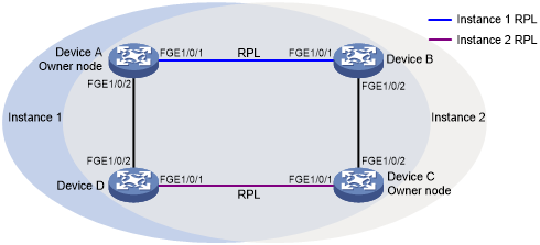
As shown in Figure 36, perform the following tasks to improve network resource utilization and implement load balancing among links:
Configure ERPS instances 1 and 2 on the ERPS ring.
For ERPS instance 1, configure the following items:
Configure Device A as the owner node.
Configure the link between Devices A and Device B as the RPL.
Configure VLAN 100 as the control VLAN.
Configure VLANs 1 to 30 as the protected VLANs.
For ERPS instance 2, configure the following items:
Configure Device A as the owner node.
Configure the link between Devices C and Device D as the RPL.
Configure VLAN 100 as the control VLAN.
Configure VLANs 31 to 60 as the protected VLANs.
Figure 36: Network diagram
Procedure
![[IMPORTANT: ]](images/important.png) | IMPORTANT: By default, interfaces on the device are disabled (in ADM or Administratively Down state). To have an interface operate, you must use the undo shutdown command to enable that interface. | |
Configure Device A.
# Create VLANs 1 to 60, map VLANs 1 to 30 to MSTI 1, map VLANs 31 to 60 to MSTI 2, and activate the MST region configuration.
<DeviceA> system-view
[DeviceA] vlan 1 to 60
[DeviceA] stp region-configuration
[DeviceA-mst-region] instance 1 vlan 1 to 30
[DeviceA-mst-region] instance 2 vlan 31 to 60
[DeviceA-mst-region] active region-configuration
[DeviceA-mst-region] quit
# Set the link state change suppression interval to 0 seconds on FortyGigE 1/0/1.
[DeviceA] interface fortygige 1/0/1
[DeviceA-FortyGigE1/0/1] link-delay 0
# Disable the spanning tree feature on the port.
[DeviceA-FortyGigE1/0/1] undo stp enable
# Configure the port as a trunk port and assign it to VLANs 1 to 60.
[DeviceA-FortyGigE1/0/1] port link-type trunk
[DeviceA-FortyGigE1/0/1] port trunk permit vlan 1 to 60
[DeviceA-] quit
# Configure FortyGigE 1/0/2 in the same way FortyGigE 1/0/1 is configured.
[DeviceA] interface
[DeviceA-FortyGigE1/0/2] link-delay 0
[DeviceA-FortyGigE1/0/2] undo stp enable
[DeviceA-] port link-type trunk
[DeviceA-FortyGigE1/0/2] port trunk permit vlan 1 to 60
[DeviceA-FortyGigE1/0/2] quit
# Create ERPS ring 1.
[DeviceA] erps ring 1
# Configure ERPS ring member ports.
[DeviceA-erps-ring1] port0 interface fortygige 1/0/1
[DeviceA-erps-ring1] port1 interface
# Create ERPS instance 1.
[DeviceA-erps-ring1] instance 1
# Configure the node role.
[DeviceA-erps-ring1-inst1] node-role owner rpl port0
# Configure the control VLAN.
[DeviceA-erps-ring1-inst1] control-vlan 100
# Configure the protected VLANs.
[DeviceA-erps-ring1-inst1] protected-vlan reference-instance 1
# Enable ERPS for instance 1.
[DeviceA-erps-ring1-inst1] instance enable
[DeviceA-erps-ring1-inst1] quit
[DeviceA-erps-ring1] quit
# Create ERPS instance 2.
[DeviceA-erps-ring1] instance 2
# Configure the control VLAN.
[DeviceA-erps-ring1-inst2] control-vlan 110
# Configure the protected VLANs.
[DeviceA-erps-ring1-inst2] protected-vlan reference-instance 2
# Enable ERPS for instance 2.
[DeviceA-erps-ring1-inst2] instance enable
[DeviceA-erps-ring1-inst2] quit
[DeviceA-erps-ring1] quit
# Enable CFD, and create a level-5 MD named MD_A.
[DeviceA] cfd enable
[DeviceA] cfd md MD_A level 5
# Create Ethernet service instance 1, in which the MA is identified by a VLAN and serves VLAN 1.
[DeviceA] cfd service-instance 1 ma-id vlan-based md MD_A vlan 1
# Configure a MEP list in Ethernet service instance 1, create outward-facing MEP 1001 in Ethernet service instance 1, and enable CCM sending on .
[DeviceA] cfd meplist 1001 1002 service-instance 1
[DeviceA] interface fortygige 1/0/1
[DeviceA-FortyGigE1/0/1] cfd mep 1001 service-instance 1 outbound
[DeviceA-FortyGigE1/0/1] cfd cc service-instance 1 mep 1001 enable
[DeviceA-FortyGigE1/0/1] quit
# Create Ethernet service instance 2, in which the MA is identified by a VLAN and serves VLAN 2.
[DeviceA] cfd service-instance 2 ma-id vlan-based md MD_A vlan 2
# Configure a MEP list in Ethernet service instance 2, create outward-facing MEP 2001 in Ethernet service instance 1, and enable CCM sending on FortyGigE 1/0/2.
[DeviceA] cfd meplist 2001 2002 service-instance 2
[DeviceA] interface fortygige 1/0/2
[DeviceA-] cfd mep 2001 service-instance 2 outbound
[DeviceA-FortyGigE1/0/2] cfd cc service-instance 2 mep 2001 enable
[DeviceA-FortyGigE1/0/2] quit
# Create track entry 1 and associate it with the CC function of CFD for MEP 1001 in Ethernet service instance 1.
[DeviceA] track 1 cfd cc service-instance 1 mep 1001
# Associate FortyGigE 1/0/1 with track entry 1 and bring up the port for ERPS instances 1 and 2.
[DeviceA] interface fortygige 1/0/1
[DeviceA-FortyGigE1/0/1] port erps ring 1 instance 1 track 1
[DeviceA-FortyGigE1/0/1] port erps ring 1 instance 2 track 1
[DeviceA-FortyGigE1/0/1] undo shutdown
[DeviceA-] quit
# Create track entry 2 and associate it with the CC function of CFD for MEP 2001 in Ethernet service instance 2.
[DeviceA] track 2 cfd cc service-instance 2 mep 2001
# Associate FortyGigE 1/0/2 with track entry 2 and bring up the port for ERPS instances 1 and 2.
[DeviceA] interface fortygige 1/0/2
[DeviceA-] port erps ring 1 instance 1 track 2
[DeviceA-FortyGigE1/0/2] port erps ring 1 instance 2 track 2
[DeviceA-FortyGigE1/0/2] undo shutdown
[DeviceA-FortyGigE1/0/2] quit
# Enable ERPS.
[DeviceA] erps enable
Configure Device B.
# Create VLANs 1 to 60, map VLANs 1 to 30 to MSTI 1, map VLANs 31 to 60 to MSTI 2, and activate the MST region configuration.
<DeviceB> system-view
[DeviceB] vlan 1 to 60
[DeviceB] stp region-configuration
[DeviceB-mst-region] instance 1 vlan 1 to 30
[DeviceB-mst-region] instance 2 vlan 31 to 60
[DeviceB-mst-region] active region-configuration
[DeviceB-mst-region] quit
# Set the link state change suppression interval to 0 seconds on FortyGigE 1/0/1.
[DeviceB] interface fortygige 1/0/1
[DeviceB-] link-delay 0
# Disable the spanning tree feature on the port.
[DeviceB-FortyGigE1/0/1] undo stp enable
# Configure the port as a trunk port and assign it to VLANs 1 to 60.
[DeviceB-FortyGigE1/0/1] port link-type trunk
[DeviceB-FortyGigE1/0/1] port trunk permit vlan 1 to 60
[DeviceB-] quit
# Configure FortyGigE 1/0/2 in the same way FortyGigE 1/0/1 is configured.
[DeviceB] interface fortygige 1/0/2
[DeviceB-FortyGigE1/0/2] link-delay 0
[DeviceB-FortyGigE1/0/2] undo stp enable
[DeviceB-] port link-type trunk
[DeviceB-FortyGigE1/0/2] port trunk permit vlan 1 to 60
[DeviceB-FortyGigE1/0/2] quit
# Create ERPS ring 1.
[DeviceB] erps ring 1
# Configure ERPS ring member ports.
[DeviceB-erps-ring1] port0 interface fortygige 1/0/1
[DeviceB-erps-ring1] port1 interface fortygige 1/0/2
# Create ERPS instance 1.
[DeviceB-erps-ring1] instance 1
# Configure the node role.
[DeviceB-erps-ring1-inst1] node-role neighbor rpl port0
# Configure the control VLAN.
[DeviceB-erps-ring1-inst1] control-vlan 100
# Configure the protected VLANs.
[DeviceB-erps-ring1-inst1] protected-vlan reference-instance 1
# Enable ERPS for instance 1.
[DeviceB-erps-ring1-inst1] instance enable
[DeviceB-erps-ring1-inst1] quit
[DeviceB-erps-ring1] quit
# Create ERPS instance 2.
[DeviceB-erps-ring1] instance 2
# Configure the control VLAN.
[DeviceB-erps-ring1-inst2] control-vlan 110
# Configure the protected VLANs.
[DeviceB-erps-ring1-inst2] protected-vlan reference-instance 2
# Enable ERPS for instance 2.
[DeviceB-erps-ring1-inst2] instance enable
[DeviceB-erps-ring1-inst2] quit
[DeviceB-erps-ring1] quit
# Enable CFD, and create a level-5 MD named MD_A.
[DeviceB] cfd enable
[DeviceB] cfd md MD_A level 5
# Create Ethernet service instance 1, in which the MA is identified by a VLAN and serves VLAN 1.
[DeviceB] cfd service-instance 1 ma-id vlan-based md MD_A vlan 1
# Configure a MEP list in Ethernet service instance 1, create outward-facing MEP 1002 in Ethernet service instance 1, and enable CCM sending on .
[DeviceB] cfd meplist 1001 1002 service-instance 1
[DeviceB] interface fortygige 1/0/1
[DeviceB-FortyGigE1/0/1] cfd mep 1002 service-instance 1 outbound
[DeviceB-FortyGigE1/0/1] cfd cc service-instance 1 mep 1002 enable
[DeviceB-FortyGigE1/0/1] quit
# Create Ethernet service instance 3, in which the MA is identified by a VLAN and serves VLAN 3.
[DeviceB] cfd service-instance 3 ma-id vlan-based md MD_A vlan 3
# Configure a MEP list in Ethernet service instance 3, create outward-facing MEP 3002 in Ethernet service instance 3, and enable CCM sending on FortyGigE 1/0/2.
[DeviceB] cfd meplist 3001 3002 service-instance 3
[DeviceB] interface fortygige 1/0/2
[DeviceB-FortyGigE1/0/2] cfd mep 3002 service-instance 3 outbound
[DeviceB-FortyGigE1/0/2] cfd cc service-instance 3 mep 3002 enable
[DeviceB-] quit
# Create track entry 1 and associate it with the CC function of CFD for MEP 1002 in Ethernet service instance 1.
[DeviceB] track 1 cfd cc service-instance 1 mep 1002
# Associate with track entry 1 and bring up the port for ERPS instances 1 and 2.
[DeviceB] interface fortygige 1/0/1
[DeviceB-] port erps ring 1 instance 1 track 1
[DeviceB-FortyGigE1/0/1] port erps ring 1 instance 2 track 1
[DeviceB-FortyGigE1/0/1] undo shutdown
[DeviceB-FortyGigE1/0/1] quit
# Create track entry 2 and associate it with the CC function of CFD for MEP 3002 in Ethernet service instance 3.
[DeviceB] track 2 cfd cc service-instance 3 mep 3002
# Associate FortyGigE 1/0/2 with track entry 2 and bring up the port for ERPS instances 1 and 2.
[DeviceB] interface fortygige 1/0/2
[DeviceB-FortyGigE1/0/2] port erps ring 1 instance 1 track 2
[DeviceB-FortyGigE1/0/2] port erps ring 1 instance 2 track 2
[DeviceB-] undo shutdown
[DeviceB-FortyGigE1/0/2] quit
# Enable ERPS.
[DeviceB] erps enable
Configure Device C.
# Create VLANs 1 to 60, map VLANs 1 to 30 to MSTI 1, map VLANs 31 to 60 to MSTI 2, and activate the MST region configuration.
<DeviceC> system-view
[DeviceC] vlan 1 to 60
[DeviceC] stp region-configuration
[DeviceC-mst-region] instance 1 vlan 1 to 30
[DeviceC-mst-region] instance 2 vlan 31 to 60
[DeviceC-mst-region] active region-configuration
[DeviceC-mst-region] quit
# Set the link state change suppression interval to 0 seconds on FortyGigE 1/0/1.
[DeviceC] interface fortygige 1/0/1
[DeviceC-FortyGigE1/0/1] link-delay 0
# Disable the spanning tree feature on the port.
[DeviceC-FortyGigE1/0/1] undo stp enable
# Configure the port as a trunk port and assign it to VLANs 1 to 60.
[DeviceC-FortyGigE1/0/1] port link-type trunk
[DeviceC-FortyGigE1/0/1] port trunk permit vlan 1 to 60
[DeviceC-] quit
# Configure FortyGigE 1/0/2 in the same way FortyGigE 1/0/1 is configured.
[DeviceC] interface fortygige 1/0/2
[DeviceC-FortyGigE1/0/2] link-delay 0
[DeviceC-FortyGigE1/0/2] undo stp enable
[DeviceC-FortyGigE1/0/2] port link-type trunk
[DeviceC-FortyGigE1/0/2] port trunk permit vlan 1 to 60
[DeviceC-FortyGigE1/0/2] quit
# Create ERPS ring 1.
[DeviceC] erps ring 1
# Configure ERPS ring member ports.
[DeviceC-erps-ring1] port0 interface fortygige 1/0/1
[DeviceC-erps-ring1] port1 interface
# Create ERPS instance 1.
[DeviceC-erps-ring1] instance 1
# Configure the control VLAN.
[DeviceC-erps-ring1-inst1] control-vlan 100
# Configure the protected VLANs.
[DeviceC-erps-ring1-inst1] protected-vlan reference-instance 1
# Enable ERPS for instance 1.
[DeviceC-erps-ring1-inst1] instance enable
[DeviceC-erps-ring1-inst1] quit
[DeviceC-erps-ring1] quit
# Create ERPS instance 2.
[DeviceC-erps-ring1] instance 2
# Configure the node role.
[DeviceC-erps-ring1-inst2] node-role owner rpl port0
# Configure the control VLAN.
[DeviceC-erps-ring1-inst2] control-vlan 110
# Configure the protected VLANs.
[DeviceC-erps-ring1-inst2] protected-vlan reference-instance 2
# Enable ERPS for instance 2.
[DeviceC-erps-ring1-inst2] instance enable
[DeviceC-erps-ring1-inst2] quit
[DeviceC-erps-ring1] quit
# Enable CFD, and create a level-5 MD named MD_A.
[DeviceC] cfd enable
[DeviceC] cfd md MD_A level 5
# Create Ethernet service instance 3, in which the MA is identified by a VLAN and serves VLAN 3.
[DeviceC] cfd service-instance 3 ma-id vlan-based md MD_A vlan 3
# Configure a MEP list in Ethernet service instance 3, create outward-facing MEP 3001 in Ethernet service instance 3, and enable CCM sending on .
[DeviceC] cfd meplist 3001 3002 service-instance 3
[DeviceC] interface fortygige 1/0/2
[DeviceC-FortyGigE1/0/2] cfd mep 3001 service-instance 3 outbound
[DeviceC-FortyGigE1/0/2] cfd cc service-instance 3 mep 3001 enable
[DeviceC-FortyGigE1/0/2] quit
# Create Ethernet service instance 4, in which the MA is identified by a VLAN and serves VLAN 4.
[DeviceC] cfd service-instance 4 ma-id vlan-based md MD_A vlan 4
# Configure a MEP list in Ethernet service instance 4, create outward-facing MEP 4001 in Ethernet service instance 4, and enable CCM sending on FortyGigE 1/0/1.
[DeviceC] cfd meplist 4001 4002 service-instance 4
[DeviceC] interface fortygige 1/0/1
[DeviceC-] cfd mep 4001 service-instance 4 outbound
[DeviceC-FortyGigE1/0/1] cfd cc service-instance 4 mep 4001 enable
[DeviceC-FortyGigE1/0/1] quit
# Create track entry 1 and associate it with the CC function of CFD for MEP 3001 in Ethernet service instance 3.
[DeviceC] track 1 cfd cc service-instance 3 mep 3001
# Associate FortyGigE 1/0/2 with track entry 1 and bring up the port for ERPS instances 1 and 2.
[DeviceC] interface fortygige 1/0/2
[DeviceC-FortyGigE1/0/2] port erps ring 1 instance 1 track 1
[DeviceC-FortyGigE1/0/2] port erps ring 1 instance 2 track 1
[DeviceC-FortyGigE1/0/2] undo shutdown
[DeviceC-FortyGigE1/0/2] quit
# Create track entry 2 and associate it with the CC function of CFD for MEP 4001 in Ethernet service instance 4.
[DeviceC] track 2 cfd cc service-instance 4 mep 4001
# Associate FortyGigE 1/0/1 with track entry 2 and bring up the port for ERPS instances 1 and 2.
[DeviceC] interface fortygige 1/0/1
[DeviceC-] port erps ring 1 instance 1 track 2
[DeviceC-FortyGigE1/0/1] port erps ring 1 instance 2 track 2
[DeviceC-FortyGigE1/0/1] undo shutdown
[DeviceC-FortyGigE1/0/1] quit
# Enable ERPS.
[DeviceC] erps enable
Configure Device D.
# Create VLANs 1 to 60, map VLANs 1 to 30 to MSTI 1, map VLANs 31 to 60 to MSTI 2, and activate the MST region configuration.
<DeviceD> system-view
[DeviceD] vlan 1 to 60
[DeviceD] stp region-configuration
[DeviceD-mst-region] instance 1 vlan 1 to 30
[DeviceD-mst-region] instance 2 vlan 31 to 60
[DeviceD-mst-region] active region-configuration
[DeviceD-mst-region] quit
# Set the link state change suppression interval to 0 seconds on FortyGigE 1/0/1.
[DeviceD] interface fortygige 1/0/1
[DeviceD-] link-delay 0
# Disable the spanning tree feature on the port.
[DeviceD-FortyGigE1/0/1] undo stp enable
# Configure the port as a trunk port and assign it to VLANs 1 to 60.
[DeviceD-FortyGigE1/0/1] port link-type trunk
[DeviceD-FortyGigE1/0/1] port trunk permit vlan 1 to 60
[DeviceD-FortyGigE1/0/1] quit
# Configure FortyGigE 1/0/2 in the same way FortyGigE 1/0/1 is configured.
[DeviceD] interface fortygige 1/0/2
[DeviceD-FortyGigE1/0/2] link-delay 0
[DeviceD-FortyGigE1/0/2] undo stp enable
[DeviceD-FortyGigE1/0/2] port link-type trunk
[DeviceD-FortyGigE1/0/2] port trunk permit vlan 1 to 60
[DeviceD-FortyGigE1/0/2] quit
# Create ERPS ring 1.
[DeviceD] erps ring 1
# Configure ERPS ring member ports.
[DeviceD-erps-ring1] port0 interface fortygige 1/0/1
[DeviceD-erps-ring1] port1 interface
# Create ERPS instance 1.
[DeviceD-erps-ring1] instance 1
# Configure the control VLAN.
[DeviceD-erps-ring1-inst1] control-vlan 100
# Configure the protected VLANs.
[DeviceD-erps-ring1-inst1] protected-vlan reference-instance 1
# Enable ERPS for instance 1.
[DeviceD-erps-ring1-inst1] instance enable
[DeviceD-erps-ring1-inst1] quit
[DeviceD-erps-ring1] quit
# Create ERPS instance 2.
[DeviceD-erps-ring1] instance 2
# Configure the node role.
[DeviceD-erps-ring1-inst2] node-role neighbor rpl port0
# Configure the control VLAN.
[DeviceD-erps-ring1-inst2] control-vlan 110
# Configure the protected VLANs.
[DeviceD-erps-ring1-inst2] protected-vlan reference-instance 2
# Enable ERPS for instance 2.
[DeviceD-erps-ring1-inst2] instance enable
[DeviceD-erps-ring1-inst2] quit
[DeviceD-erps-ring1] quit
# Enable CFD, and create a level-5 MD named MD_A.
[DeviceD] cfd enable
[DeviceD] cfd md MD_A level 5
# Create Ethernet service instance 2, in which the MA is identified by a VLAN and serves VLAN 2.
[DeviceD] cfd service-instance 2 ma-id vlan-based md MD_A vlan 2
# Configure a MEP list in Ethernet service instance 2, create outward-facing MEP 2002 in Ethernet service instance 2, and enable CCM sending on .
[DeviceD] cfd meplist 2001 2002 service-instance 2
[DeviceD] interface fortygige 1/0/2
[DeviceD-FortyGigE1/0/2] cfd mep 2002 service-instance 2 outbound
[DeviceD-FortyGigE1/0/2] cfd cc service-instance 2 mep 2002 enable
[DeviceD-FortyGigE1/0/2] quit
# Create Ethernet service instance 4, in which the MA is identified by a VLAN and serves VLAN 4.
[DeviceD] cfd service-instance 4 ma-id vlan-based md MD_A vlan 4
# Configure a MEP list in Ethernet service instance 4, create outward-facing MEP 4002 in Ethernet service instance 4, and enable CCM sending on FortyGigE 1/0/1.
[DeviceD] cfd meplist 4001 4002 service-instance 4
[DeviceD] interface fortygige 1/0/1
[DeviceD-] cfd mep 4002 service-instance 4 outbound
[DeviceD-FortyGigE1/0/1] cfd cc service-instance 4 mep 4002 enable
[DeviceD-FortyGigE1/0/1] quit
# Create track entry 1 and associate it with the CC function of CFD for MEP 2002 in Ethernet service instance 2.
[DeviceD] track 1 cfd cc service-instance 2 mep 2002
# Associate FortyGigE 1/0/2 with track entry 1 and bring up the port for ERPS instances 1 and 2.
[DeviceD] interface fortygige 1/0/2
[DeviceD-FortyGigE1/0/2] port erps ring 1 instance 1 track 1
[DeviceD-FortyGigE1/0/2] port erps ring 1 instance 2 track 1
[DeviceD-FortyGigE1/0/2] undo shutdown
[DeviceD-] quit
# Create track entry 2 and associate it with the CC function of CFD for MEP 4002 in Ethernet service instance 4.
[DeviceD] track 2 cfd cc service-instance 4 mep 4002
# Associate FortyGigE 1/0/1 with track entry 2 and bring up the port for ERPS instances 1 and 2.
[DeviceD] interface fortygige 1/0/1
[DeviceD-] port erps ring 1 instance 1 track 2
[DeviceD-FortyGigE1/0/1] port erps ring 1 instance 2 track 2
[DeviceD-FortyGigE1/0/1] undo shutdown
[DeviceD-FortyGigE1/0/1] quit
# Enable ERPS.
[DeviceD] erps enable
Verifying the configuration
# Display information about ERPS instance 1 for Device A.
[Device A] display erps detail ring 1
 Ring ID               : 1
 Port0                 : FortyGigE1/0/1
 Port1                 : FortyGigE1/0/2
 Subring               : No
 Default MAC           : No
 Instance ID           : 1
 Node role             : Owner
 Node state            : Idle
 Connect(ring/instance): -
 Control VLAN          : 100
 Protected VLAN        : Reference-instance 1
 Guard timer           : 500 ms
 Hold-off timer        : 0 ms
 WTR timer             : 5 min
 Revertive operation   : Revertive
 Enable status         : Yes, Active status : Yes
 R-APS level           : 7
 Port                  PortRole                PortStatus
 ----------------------------------------------------------------------------
 Port0                 RPL                     Block
 Port1                 Non-RPL                 Up

 Instance ID           : 2
 Node role             : Normal
 Node state            : Idle
 Connect(ring/instance): -
 Control VLAN          : 100
 Protected VLAN        : Reference-instance 2
 Guard timer           : 500 ms
 Hold-off timer        : 0 ms
 WTR timer             : 5 min
 Revertive operation   : Revertive
 Enable status         : Yes, Active status : Yes
 R-APS level           : 7
 Port                  PortRole                PortStatus
 ----------------------------------------------------------------------------
 Port0                 Non-RPL                 Up
 Port1                 Non-RPL                 Up
The output shows the following information:
For ERPS instance 1:
Device A is the owner node.
The ERPS ring is in idle state.
The RPL port is blocked.
The non-RPL port is unblocked.
For ERPS instance 2:
Device A is a normal node.
The ERPS ring is in idle state.
The non-RPL port is unblocked.