Typical RRPP networking
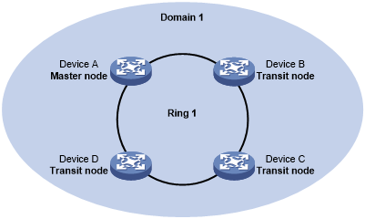
Single ring
As shown in Figure 14, only a single ring exists in the network topology. You need only define an RRPP domain.
Figure 14: Schematic diagram for a single-ring network
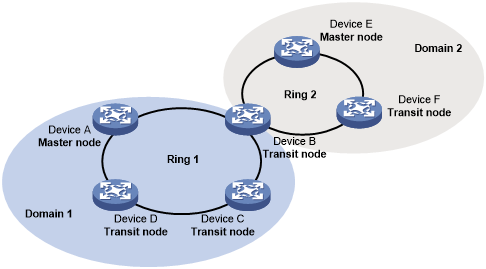
Tangent rings
As shown in Figure 15, two or more rings exist in the network topology and only one common node exists between rings. You must define an RRPP domain for each ring.
Figure 15: Schematic diagram for a tangent-ring network
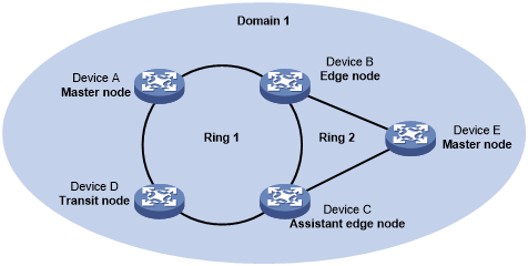
Intersecting rings
As shown in Figure 16, two or more rings exist in the network topology and two common nodes exist between rings. You need only define an RRPP domain and configure one ring as the primary ring and the other rings as subrings.
Figure 16: Schematic diagram for an intersecting-ring network
Dual-homed rings
As shown in Figure 17, two or more rings exist in the network topology and two similar common nodes exist between rings. You need only define an RRPP domain and configure one ring as the primary ring and the other rings as subrings.
Figure 17: Schematic diagram for a dual-homed-ring network
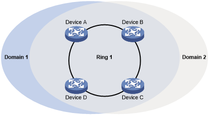
Single-ring load balancing
In a single-ring network, you can achieve load balancing by configuring multiple domains.
As shown in Figure 18:
Ring 1 is configured as the primary ring of both Domain 1 and Domain 2.
Domain 1 and Domain 2 are configured with different protected VLANs.
In Domain 1, Device A is configured as the master node of Ring 1.
In Domain 2, Device B is configured as the master node of Ring 1.
Such configurations enable the ring to block different links based on VLANs and achieve single-ring load balancing.
Figure 18: Schematic diagram for a single-ring load balancing network
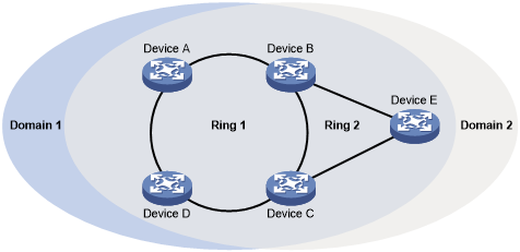
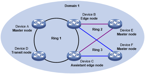
Intersecting-ring load balancing
In an intersecting-ring network, you can also achieve load balancing by configuring multiple domains.
As shown in Figure 19:
Ring 1 is the primary ring and Ring 2 is the subring in both Domain 1 and Domain 2.
Domain 1 and Domain 2 are configured with different protected VLANs.
Device A is configured as the master node of Ring 1 in Domain 1.
Device D is configured as the master node of Ring 1 in Domain 2.
Device E is configured as the master node of Ring 2 in both Domain 1 and Domain 2. However, different ports on Device E are blocked in Domain 1 and Domain 2.
Traffic from different VLANs can travel over different paths in the subring and primary ring.
Figure 19: Schematic diagram for an intersecting-ring load balancing network