RRPP networking
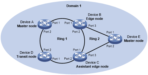
Figure 13 shows a typical RRPP network with two Ethernet rings and multiple nodes. RRPP detects ring status and sends topology change information by exchanging Rapid Ring Protection Protocol Data Units (RRPPDUs) among the nodes.
Figure 13: RRPP networking diagram
RRPP domain
An RRPP domain is uniquely identified by a domain ID. The interconnected devices with the same domain ID and control VLANs constitute an RRPP domain. An RRPP domain contains the following elements:
Primary ring and subring.
Control VLAN.
Master node, transit node, edge node, and assistant edge node.
Primary port, secondary port, common port, and edge port.
As shown in Figure 13, Domain 1 is an RRPP domain, containing two RRPP rings: Ring 1 and Ring 2. All the nodes on the two RRPP rings belong to the RRPP domain.
RRPP ring
A ring-shaped Ethernet topology is called an RRPP ring. RRPP rings include primary rings and subrings. You can configure a ring as either the primary ring or a subring by specifying its ring level. The primary ring is of level 0, and a subring is of level 1. An RRPP domain contains one or multiple RRPP rings, one serving as the primary ring and the others serving as subrings. A ring can be in one of the following states:
Health state—All physical links on the Ethernet ring are connected.
Disconnect state—Some physical links on the Ethernet ring are not connected.
As shown in Figure 13, Domain 1 contains two RRPP rings: Ring 1 and Ring 2. The level is set to 0 for Ring 1 and 1 for Ring 2. Ring 1 is configured as the primary ring, and Ring 2 is configured as a subring.
Control VLAN and protected VLAN
Control VLAN
In an RRPP domain, a control VLAN is dedicated to transferring RRPPDUs. On a device, the ports accessing an RRPP ring belong to the control VLANs of the ring, and only these ports can join the control VLANs.
An RRPP domain is configured with the following control VLANs:
One primary control VLAN, which is the control VLAN for the primary ring.
One secondary control VLAN, which is the control VLAN for subrings.
After you specify a VLAN as the primary control VLAN, the system automatically configures the secondary control VLAN. The VLAN ID is the primary control VLAN ID plus one. All subrings in the same RRPP domain share the same secondary control VLAN. IP address configuration is prohibited on the control VLAN interfaces.
Protected VLAN
A protected VLAN is dedicated to transferring data packets. Both RRPP ports and non-RRPP ports can be assigned to a protected VLAN.
Node role
Each device on an RRPP ring is a node. The role of a node is configurable. RRPP has the following node roles:
Master node—Each ring has only one master node. The master node initiates the polling mechanism and determines the operations to be performed after a topology change.
Transit node—On the primary ring, transit nodes refer to all nodes except the master node. On the subring, transit nodes refer to all nodes except the master node and the nodes where the primary ring intersects with the subring. A transit node monitors the state of its directly connected RRPP links and notifies the master node of the link state changes, if any. Based on the link state changes, the master node determines the operations to be performed.
Edge node—A special node residing on both the primary ring and a subring at the same time. An edge node acts as a master node or transit node on the primary ring and as an edge node on the subring.
Assistant edge node—A special node residing on both the primary ring and a subring at the same time. An assistant edge node acts as a master node or transit node on the primary ring and as an assistant edge node on the subring. This node works in conjunction with the edge node to detect the integrity of the primary ring and to perform loop guard.
As shown in Figure 13, Ring 1 is the primary ring and Ring 2 is a subring. Device A is the master node of Ring 1. Device B, Device C, and Device D are the transit nodes of Ring 1. Device E is the master node of Ring 2, Device B is the edge node of Ring 2, and Device C is the assistant edge node of Ring 2.
Port role
Primary port and secondary port
Each master node or transit node has two ports connected to an RRPP ring, a primary port and a secondary port. You can determine the role of a port.
In terms of functionality, the primary port and the secondary port of a master node have the following differences:
The primary port and the secondary port are designed to play the role of sending and receiving Hello packets, respectively.
When an RRPP ring is in Health state, the secondary port logically denies protected VLANs and permits only the packets from the control VLANs.
When an RRPP ring is in Disconnect state, the secondary port forwards packets from protected VLANs.
In terms of functionality, the primary port and the secondary port of a transit node are the same. Both are designed for transferring protocol packets and data packets over an RRPP ring.
As shown in Figure 13, Device A is the master node of Ring 1. Port 1 and Port 2 are the primary port and the secondary port of the master node on Ring 1, respectively. Device B, Device C, and Device D are the transit nodes of Ring 1. Their Port 1 and Port 2 are the primary port and the secondary port on Ring 1, respectively.
Common port and edge port
The ports connecting the edge node and assistant edge node to the primary ring are common ports. The ports connecting the edge node and assistant edge node only to the subrings are edge ports. You can determine the role of a port.
As shown in Figure 13, Device B and Device C reside on Ring 1 and Ring 2. Device B's Port 1 and Port 2 and Device C's Port 1 and Port 2 access the primary ring, so they are common ports. Device B's Port 3 and Device C's Port 3 access only the subring, so they are edge ports.
RRPP ring group
To reduce Edge-Hello traffic, you can configure a group of subrings on the edge node or assistant edge node. You must configure a device as the edge node of these subrings, and another device as the assistant edge node of these subrings. Additionally, the subrings of the edge node and assistant edge node must connect to the same subring packet tunnels in major ring (SRPTs). Edge-Hello packets of the edge node of these subrings travel to the assistant edge node of these subrings over the same link.
An RRPP ring group configured on the edge node is an edge node RRPP ring group. An RRPP ring group configured on an assistant edge node is an assistant edge node RRPP ring group. Only one subring in an edge node RRPP ring group is allowed to send Edge-Hello packets.