How DLDP works
Detecting one neighbor
When two devices are connected through an optical fiber or a network cable, enable DLDP to detect unidirectional links to the neighbor. The following illustrates the unidirectional link detection process in two cases:
Unidirectional links occur before you enable DLDP.
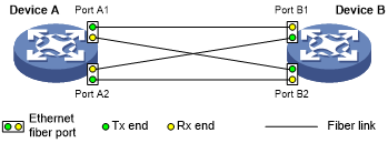
Figure 7: Cross-connected fibers
As shown in Figure 7, before you enable DLDP, the optical fibers between Device A and Device B are cross-connected. After you enable DLDP, the four ports are all up and in unidirectional state, and they send RecoverProbe packets. Take Port A1 as an example to illustrate the unidirectional link detection process.
Port A1 receives the RecoverProbe packet from Port B2, and returns a RecoverEcho packet.
Port B2 cannot receive any RecoverEcho packet from Port A1, so Port B2 cannot become the neighbor of Port A1.
Port B1 can receive the RecoverEcho packet from Port A1, but Port B1 is not the intended destination, so Port B1 cannot become the neighbor of Port A1.
The same process occurs on the other three ports. The four ports are all in unidirectional state.
Unidirectional links occur after you enable DLDP.
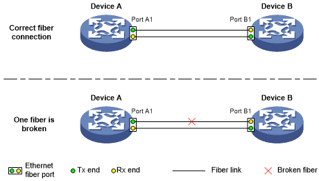
Figure 8: Broken fiber
As shown in Figure 8, Device A and Device B are connected through an optical fiber. After you enable DLDP, Port A1 and Port B1 establish the bidirectional neighborship in the following way:
Port A1 that is physically up enters the unidirectional state and sends a RecoverProbe packet.
After receiving the RecoverProbe packet, Port B1 returns a RecoverEcho packet.
After Port A1 receives the RecoverEcho packet, it examines the neighbor information in the packet. If the neighbor information matches the local information, Port A1 establishes the neighborship with Port B1 and transits to bidirectional state. Port A1 then starts the Entry timer and periodically sends Advertisement packets.
After Port B1 receives the Advertisement packet, it establishes the Unconfirmed neighborship with Port A1. Port B1 then starts the Echo timer and Probe timer, and periodically sends Probe packets.
After receiving the Probe packet, Port A1 returns an Echo packet.
After Port B1 receives the Echo packet, it examines the neighbor information in the packet. If the neighbor information matches the local information, the neighbor state of Port A1 becomes Confirmed. Port B1 then transits to bidirectional state, starts the Entry timer, and periodically sends Advertisement packets.
The bidirectional neighborship between Port A1 and Port B1 is now established.
After that, when Port B1's Rx end fails to receive signals, Port B1 is physically down and enters the Inactive state. Because Port B1's Tx end can still send signals to Port A1, Port A1 stays up. After the Entry timer for Port B1 expires, Port A1 starts the Enhanced timer and Echo timer, and sends a probe packet to Port B1. Because Port A1's Tx line is broken, Port A1 cannot receive the Echo packet from Port B1 after the Echo timer expires. Port A1 then enters the unidirectional state, and sends a Disable packet to Port B1. At the same time, Port A1 deletes the neighborship with Port B1, and starts the RecoverProbe timer. Port B1 stays in Inactive state during this process.
When an interface is physically down, but the Tx end of the interface is still operating, DLDP sends a LinkDown packet to inform the peer to delete the relevant neighbor entry.
Detecting multiple neighbors
When multiple devices are connected through a hub, enable DLDP on all interfaces connected to the hub to detect unidirectional links among the neighbors. When no Confirmed neighbor exists, an interface enters the unidirectional state.
Figure 9: Network diagram
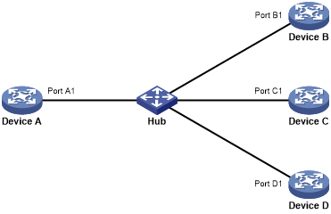
As shown in Figure 9, Device A through Device D are connected through a hub, and enabled with DLDP. When Port A1, Port B1, and Port C1 detect that the link to Port D1 fails, they delete the neighborship with Port D1, but stay in bidirectional state.